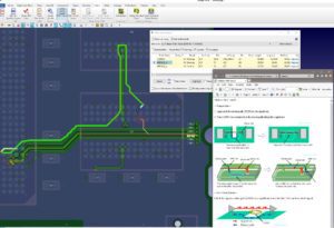
Select and configure from 42 rules in 6 categories

Are you looking for a tool that enables you to meet the EMC requirements for your products? Then EMC Adviser EX is exactly the right solution for you! Using EMC Adviser speeds up the identification of EMC issues in an early design phase with reduced effort compared to manual checks.
Select and configure from 42 rules in 6 categories

Cross-probe and highlight within the design

Create summary reports and share as MS-Excel documents
With EMC Adviser for CR-8000, the circuit engineer is able to categorize EMC-relevant signals early-on in the schematic phase. The appropriate EMC rules are selected for the application and applied during the design phase, such as a DRC check.
EMC Adviser’s guidelines provide design issue recommendations, enabling non-expert users to solve Signal Integrity, Power Integrity, and EMC issues. Users can choose and configure from 42 rules in 6 categories, generate check results, cross-select, and highlight within the PCB layout, and create summary reports.
Summary reports with images and progress status can be shared as MS-Excel documents between the members of the development team. There is no need for any additional software to verify the identified EMC issues.
Related Webinars
In this Webinar, you will discover how to streamline your PCB design process with CR-8000, and seamlessly integrate prototype testing results using NoiseKen for enhanced accuracy and performance.
In this Webinar, an optimized PCB design flow combining Zuken CR-8000 technology working tightly with stackup optimization capabilities provided by Polar Speedstack ™ will be presented.
Using the example of the analysis of SerDes transmission paths such as PCI Express, SATA or USB3, we explain the methodology of an analysis- and constraint-driven assembly development with CR-8000 Design Force.
EMC Adviser EX can be launched from these products
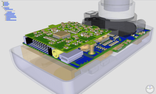
CR-8000 Design Force is the fastest, most effective PCB design solution available today. Design Force enables design teams to layout and verify their designs in the context of a complete system or product.
Design Force offers an intuitive, integrated environment for designing single and multi-die packages for wire-bond, flip-chip, and high density advanced IC packaging.
Recent EMC Adviser EX Blog Posts
EMC problems are often responsible for re-design cycles in PCB design practice. Due to ever shorter innovation cycles of for example cell phones or IoT applications, such as fitness trackers or smartwatches, and many other electronic products, these time-consuming re-design cycles should be avoided under all circumstances.
In part 1 of this blog we took a back-to-basics approach and discussed line impedance and its effects in signal integrity. As every electrical conductor comprises capacitance, an inductance, and a frequency-dependent ohmic resistance, and with increasing frequencies, these electrical characteristics will influence and distort the signal.
Impedance and impedance control are some of the oldest and most discussed topics in PCB design. They are especially important in high-speed design related to signal integrity. In this, the first of a two-part blog, we’ll go back to the basics of impedance/impedance control and consider what influences line impedance. In part two, we’ll set about controlling it.