An integrated design solution for interconnecting devices and designing cables and wire harnesses
E3.cable is a powerful electrical wiring design software, used for designing and documenting cable plans and wire harness layouts. Extending the functionality of E3.schematic, it enables individual conductors to be combined together in the design to form cables or harnesses. Shielding and twisted-pair structure can also be added to the cables and automatically shown in the schematic. E3.cable is ideally suited for industries developing power and wire harnesses for the automotive, off-highway and special purpose vehicle, and aerospace industries, or those developing field cabling for plant and machinery.
An integrated design solution for interconnecting devices and designing cables and wire harnesses
Intelligent block functionality enabling the representation of dynamic equipment
Hierarchy functionality for flexible top-down or bottom-up design approach
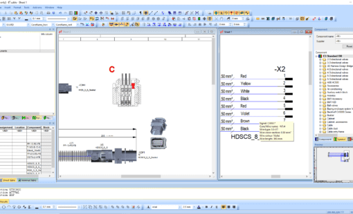
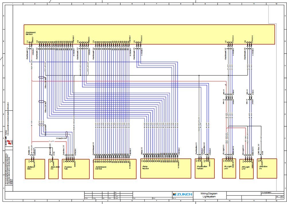
Multiple views of devices for design and documentation purposes
E3.cable supports block functionality for electrical wiring design: blocks can represent components, rack equipment, black boxes, PCBs, and through hierarchy whole systems and sub-systems. Connector pins are dynamically added to the blocks and signal information is displayed alongside.
Views allow alternate documentation of devices such as single-line diagrams, wiring diagrams, and cable plans. For example, connectors can be represented as single pins in the schematic and then as the complete connector in the cable plan. Changes to any of the views, immediately update all other views, ensuring all documentation is synchronized.
See how easy it is to work with E3.cable
E3.cable supports block functionality for electrical wiring design: blocks can represent components, rack equipment, black boxes, PCBs, and whole systems and sub-systems. Connector pins are dynamically added to the blocks, and signal information is displayed alongside.
Views allow alternate representations such as single-line diagrams, wiring diagram and cable plans. Connectors can be represented as single pins in the schematic and then as the complete connector in the cable plan. Changes to any of the views, are immediately updated all related views.
Hierarchical systems and sub-systems can be represented as blocks. Signals and connections can pass between levels and sub-levels. Hierarchy enables top-down and bottom-up design, promotes design reuse and provides project leaders with a system level overview.
Blocks can be integrated with PCB design data. Interface connector and signal information from the PCB system is dynamically added to the blocks in E3.series. Changes to the PCB are re-imported and updated in the block. E3.cable supports most PCB formats and has bi-directional integrations with Zuken’s CR-8000.
Satisfied customers
Related Products
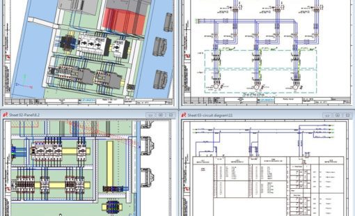
E3.panel allows engineers to layout components inside panel enclosures in both 3D and 2D. Intelligent automatic snapping points allow parts to be easily placed in their correct location.
Related Resources
Find out more about via our case studies, datasheets and more.
The new release focuses on minimizing repetitive tasks, improving data integrity, and accelerating project timelines - particularly for designs involving complex variants, large component libraries, or integrated 2D/3D workflows.
Haulotte's choice of Zuken's E3.series solution has enabled the optimization of work methodology and a more serene and effective projection towards future developments
This webinar will cover the design of large electrical projects. A vital element of the design process is the tracking of nomenclature, device and cable functions, assignments and placement.
This webinar follows looks at the physical part of the wire harness design process: Routing of the harness in the physical (3D) design space
This webinar covers the logical part of the wire harness design process consisting of creating the wiring diagram and the topology design.
Recent E3.cable Blog Posts
Build accurate dynamic cables in E3.series by defining cores, shields, and twisted pairs so schematics, reports, and formboard outputs stay consistent.
E3.series automation is entering a new era as Microsoft phases out VBS. With the official Python package, Zuken offers a modern, future-proof way to automate E3.series while preserving all familiar capabilities.
Use Fields in E3.series to stop splitting designs across multiple pages, keep device inheritance correct, and generate clean reports when multiple functions share one sheet.
Use Fields in E3.series to stop splitting designs across multiple pages, keep device inheritance correct, and generate clean reports when multiple functions share one sheet.
Despite the best intentions of design engineers, seemingly perfect schematics can unravel the moment they hit the shop floor, especially in wire harness and control cabinet manufacturing. When tiny oversights spark major production headaches, the real question becomes: how can smarter design tools finally close this costly gap?
Learn how E3.formboard turns schematics into build-ready harness layouts - lengths, splices, tables, protection, and EMC - for faster, repeatable shop-floor assembly.