Create functional sketches in a digitally reusable format
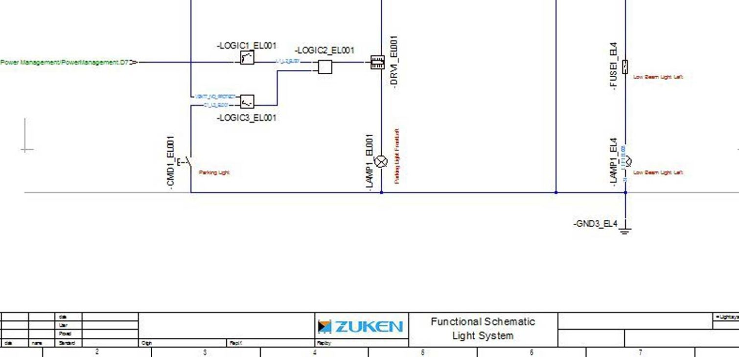
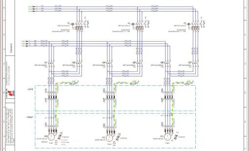
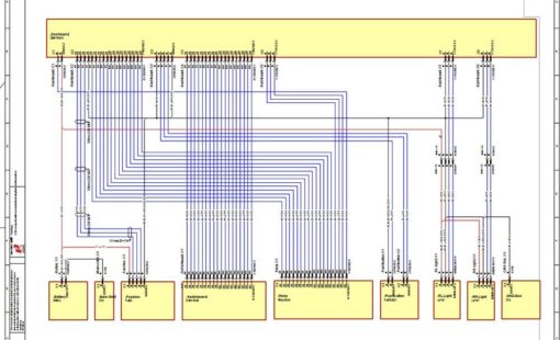
In the development of electrical and electronic systems, sketches are often drawn at the beginning of a project to describe high-level functionality and the communication channels between individual modules. The electrical drawing software E3.FunctionalDesign supports the development of those first sketches which can then be used to drive the detailed wiring and fluid plans.
Create functional sketches in a digitally reusable format

Define system functions at a high level

Provide concept sketches for bidding processes

Specify and Communicate details to wiring diagram development
The electrical drawing software automatically connects all components with the same signal and displays this mapping in properties that are stored in the dynamic components. Functional units can be moved between dynamic components at any time with the affected signals being immediately updated on the connection points.
After the desired functional units of a dynamic component are correctly assigned, the dynamic component is replaced by a standard component from the library. These standard components include the additional information needed to complete the project, such as connector, mating connector, and connector pin terminals.
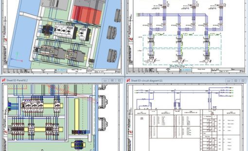
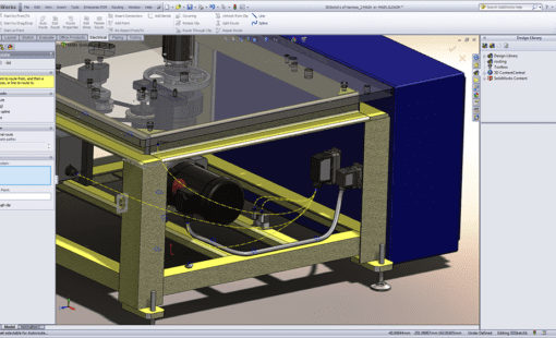
The designs can later be detailed using the full E3.series environment.
Related Resources
Find out more via our webinars, blogs, press releases and more...
This webinar covers the logical part of the wire harness design process consisting of creating the wiring diagram and the topology design.
This webinar follows looks at the physical part of the wire harness design process: Routing of the harness in the physical (3D) design space
Related Products
E3.cable extends the functionality of E3.schematic enabling individual conductors to be combined together in the design to form cables and harnesses.
E3.panel allows engineers to layout components inside panel enclosures in both 3D and 2D. Intelligent automatic snapping points allow parts to be easily placed in their correct location.
E3.3DRouting Bridge - Streamline ECAD-MCAD collaboration by synchronizing connectivity data between E3.series and leading MCAD platforms in real-time.