signal integrity simulation and power integrity analysis

PCB Simulation and Analysis

Signal Integrity, Power Integrity, EMC
Menu

A Complete PCB Simulation and Analysis Environment

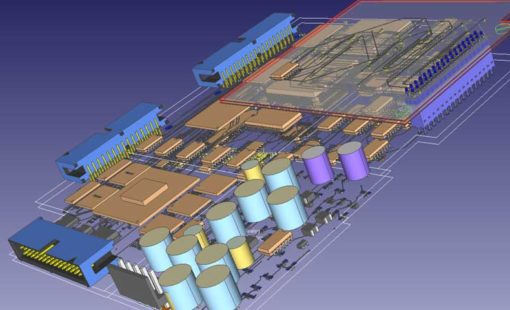
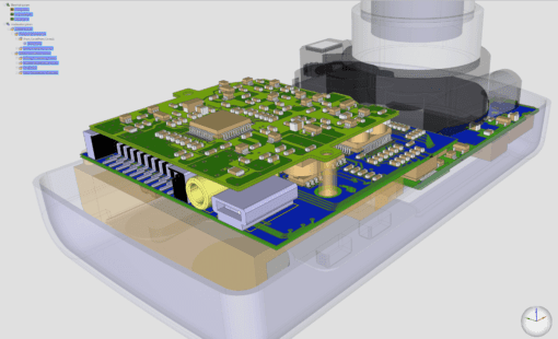
With its comprehensive suite of features, CR-8000 offers a complete environment to simulate and analyze your printed circuit board designs. Whether you're working on a single-board or multi-board project, this powerful software provides everything you need to ensure the integrity and reliability of your PCB designs.

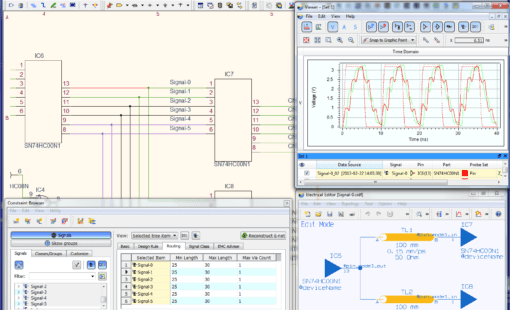
During circuit design, Design Gateway provides embedded simulation, analysis and electrical rules checking.

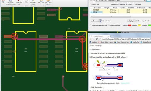
During PCB layout, Design Force provides embedded power and signal integrity analysis and electromagnetic interference checks.

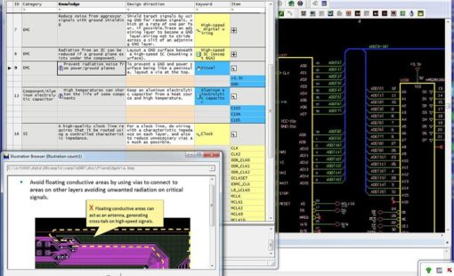
Electromagnetic compatibility tools provide a single environment for all of your design team’s simulation and analysis requirements

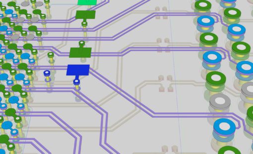
Signal Integrity Simulation

  • Constraining and topology planning in pre-layout phase
  • Impedance planning with integrated field solver using lossy interconnect models
  • Fast interactive time domain simulation for precise timing, reflection, and crosstalk analysis
  • Consider IBIS Buffer models
  • Use SPICE and S-parameter based models in time-domain
  • Inspect automatic timing, skew, and signal integrity measurement results
  • Optimize topology by use of parameter sweeps
  • Evaluate crosstalk in coupled topologies and scenarios
  • Explore the impact of manufacturing tolerances and material properties on the signal integrity behaviour
  • Utilize comprehensive signal integrity simulation library model management
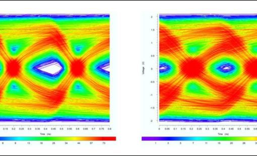
  • Time-domain Eye Pattern Analysis for parallel busses and serial links
  • Inspect Setup and Hold timing
  • Define Eye Masks and measure against them
  • Time Domain Reflectometry for interconnect optimization
  • Drive TDR-Analysis with different speed levels
  • Inspect TDR impedances for single line and differential pair interconnects
  • Consider feed-in/out lines
  • Wideband S-Parameter calculation for interconnect optimization up to 15 GHz
  • Inspect Mixed-mode S-Parameters
  • Export S-Parameters to Touchstone files
  • Enforce causality where needed
  • AMI simulation for gigabit SERDES channel optimization
  • Characterize serial links (S-Parameter, Transfer function, Impulse response)
  • Consider various types of Jitter (TX and RX)
  • Easy-to-use parameterization of AMI models
  • Inspect time-domain waveforms
  • Visualize Eye Pattern and Bathtub curves
  • Measure Eye Openings
  • Calculate Bit Error Ratio (BER)

EMI and Power Integrity Analysis

  • Full board, fast und efficient EMI screening tool identifying major EMI sources
  • Evaluate common mode and differential mode emissions
  • Visualize I/O crosstalk regions
  • Consider various antenna mechanisms
  • Wideband PI-Analysis of supply systems up to 15 GHz
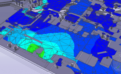
  • Detect and visualize high AC-impedance regions in supply systems, exploring root causes of resonances
  • Evaluate Decap efficiency and mounting inductances, visualize Decap impedances
  • Define virtual Decaps for what-if scenarios
  • Optimize decoupling strategies, identifying “fear”-Decaps
  • DC-Analysis of supply systems identifying voltage drops and high current load regions
  • Visualize DC-current and -voltage distribution
  • Identify insufficient supply voltages at IC power pins
  • Identify stressed Vias under high DC-current load
  • Extract DC-resistances between power pins
  • Drive supply system with alternative voltage sources for what-if’s

Learn how CR-8000 can benefit you

Receive a demo tailored to your business needs.
Request Evaluation of CR-8000

Related Resources

Figure-5-serdes-link-simulation-1024x474-1-510x310
  • Webinar
July 12, 2022
Analysis and constraint-driven PCB Design with CR-8000 using analysis of SerDes

Using the example of the analysis of SerDes transmission paths such as PCI Express, SATA or USB3, we explain the methodology of an analysis- and constraint-driven assembly development with CR-8000 Design Force.

Watch Now
Signal Integrity
  • Webinar
August 13, 2021
Solving LPDDR4 Technology Design Challenges

In this presentation you will be introduced to the necessary steps in constraining and validation of LPDDR4 on the basis of a real design realized in CR-8000 Design Force right first time.

Watch Now
CR-8000 R2021
  • Press Release
July 07, 2021
Zuken’s CR-8000 2021 Advances Early Design Analysis and Reuse Functionality

CR-8000 advances system-level PCB design with significant enhancements in analog simulation, SI analysis, and intelligent layout and routing

Read now
CR-8000-2020-SI-wave-600x300-1-510x310
  • Webinar
July 06, 2020
Practical Signal Integrity for improved EMI Control in PCB Design

In our webinar we will provide an introduction to the challenges of signal integrity and the underlying physical effects. This will provide the basis for practical tips to address the related challenges during PCB design.

WATCH NOW
cr8000-2020-design-force-pcb-board-510x310
  • Case Study
June 30, 2020
ONTEC

ONTEC faced a difficult challenge: develop a multimedia broadcasting product while complying with a customer’s electromagnetic interference requirements, all within a tight development schedule. ONTEC used Zuken’s CR-8000 with Keysight’s ADS (including SiPro) to meet the requirements of the challenge

Read now
ONTEC uses CR-8000 to develop a next-generation product in less time despite rigorous design constraints
EMC for PCB Designers
  • Webinar
May 04, 2020
EMC for PCB Designers

In this presentation, an EMC minded PCB design approach is presented, allowing designers to understand which EMC rules will apply to PCB projects and how EMC analysis capabilities can be utilized in the CAD flow to reduce the risk of EMC compliance failure once the board is manufactured.

Read now

Related Blog Posts

ddr5 designs
  • Blog
October 17, 2019
Be First to Market with DDR5!

Double Data Rate 5 (DDR5) is the next-generation standard for random-access memory (RAM). The new specification promises to bring chips that have much higher performance than the existing DDR4 modules, as well as lower power consumption. Let us show you how you can be first to market with DDR5!

Read now
An intricate network of pink and blue illuminated lines on a circuit board, symbolizing high-speed signal paths and the precision needed to calculate trace length from time delay values.
  • Blog
July 11, 2019
How to Calculate Trace Length for High-speed Signals

To keep a good high-speed signal quality from driver to receiver on a PCB is not an easy task for designers. One of the most challenging issues is managing the propagation delay and relative time delay mismatches. Let me take you through the process...

Read now
High-speed stealth fighter jet mid-flight demonstrating agility and speed, symbolizing advanced DDR4 technology capabilities
  • Blog
June 27, 2019
Who’s afraid of DDR4?

What IC designers do to help us route high-speed PCBs

Read now
lights curving through the darkness, illustrating the concept of electrical impedance control in circuit design
  • Blog
February 28, 2019
Inside Signal Integrity: Impedance Control - Part 2

In part 1 of this blog we took a back-to-basics approach and discussed line impedance and its effects in signal integrity. As every electrical conductor comprises capacitance, an inductance, and a frequency-dependent ohmic resistance, and with increasing frequencies, these electrical characteristics will influence and distort the signal.

Read now
Signal Integrity Basics: Impedance Control
  • Blog
February 21, 2019
Inside Signal Integrity: Impedance Control - Part 1

Impedance and impedance control are some of the oldest and most discussed topics in PCB design. They are especially important in high-speed design related to signal integrity. In this, the first of a two-part blog, we’ll go back to the basics of impedance/impedance control and consider what influences line impedance. In part two, we’ll set about controlling it.

Read now
differential-pairs-featured-img-510x310
  • Blog
August 16, 2018
What You Really Need to Know When You're Routing PCB Differential Pairs

Tips for when routing differential pairs - You can tell when something isn’t as clear as it should be. The same questions come up time and again. You ask three experts and get three different answers. Routing differential pairs can be like that. Why? Because “it depends” - on exactly what signals those pairs are carrying and what kind of PCB you’re creating.

Read now

Got a Question? - Contact Zuken today

For more information on how Zuken can help your design process, contact Zuken today.
Contact us today