Rules based layout adviser tools provide rapid electromagnetic radiation and susceptibility checks
As data rates rise and margins shrink, PCB design leaves little room for trial-and-error. Small shifts in impedance, return-path geometry, or PDN behavior can derail a high-speed interface long before a prototype reaches the lab. That’s why simulation and analysis are essential. They expose signal distortion, power delivery weaknesses, and EMI risks early enough to correct them, avoiding costly redesigns and compliance surprises.
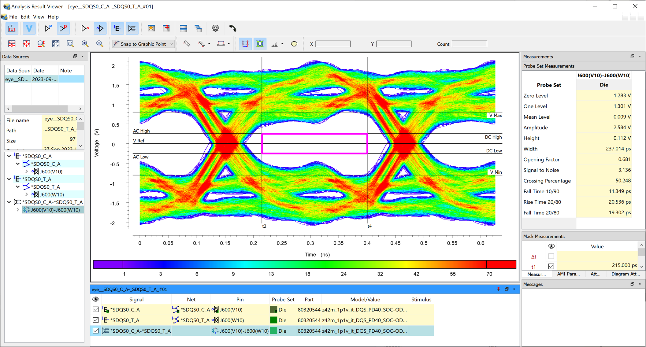
Zuken’s CR-8000 embedded simulation suite addresses this by bringing signal integrity, power integrity, and EMI-aware analysis directly into the design flow. Engineers can evaluate stack-ups, routing strategies, differential pairs, PDN behavior, crosstalk, and eye diagrams as the layout evolves. This integrated approach reduces board spins, improves high-speed reliability, and helps ensure designs meet performance and compliance targets the first time.
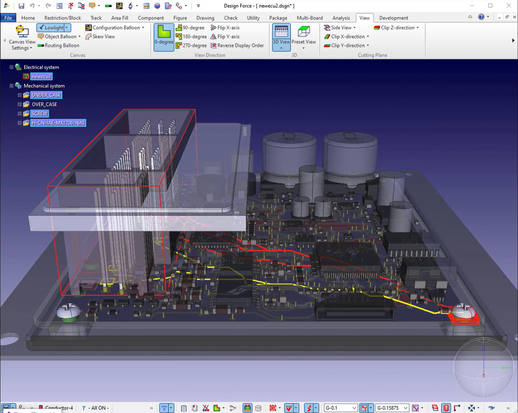
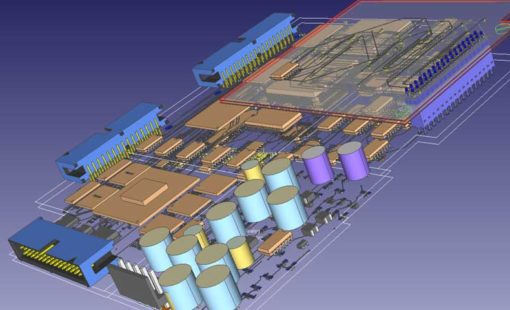
With its comprehensive suite of applications CR-8000 offers a complete environment to simulate and analyze your printed circuit board designs. Whether you're working on a single-board or multi-board project, this powerful software provides everything you need to ensure the integrity and reliability of your PCB designs.
Rules based layout adviser tools provide rapid electromagnetic radiation and susceptibility checks

Embedded simulation, analysis and electrical rules checking during circuit design.

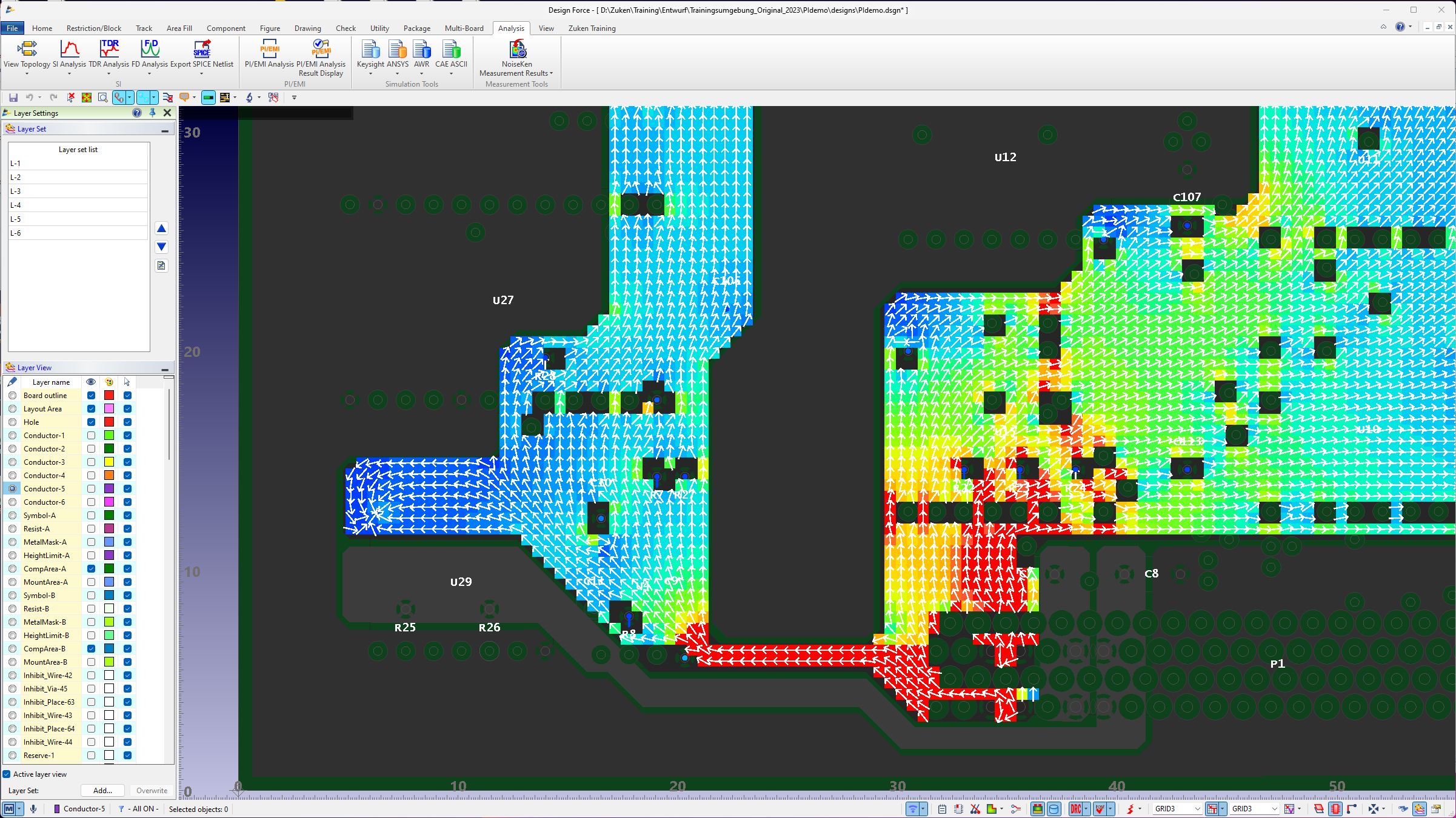
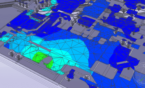
Power and signal integrity analysis, and electromagnetic interference checks during PCB layout
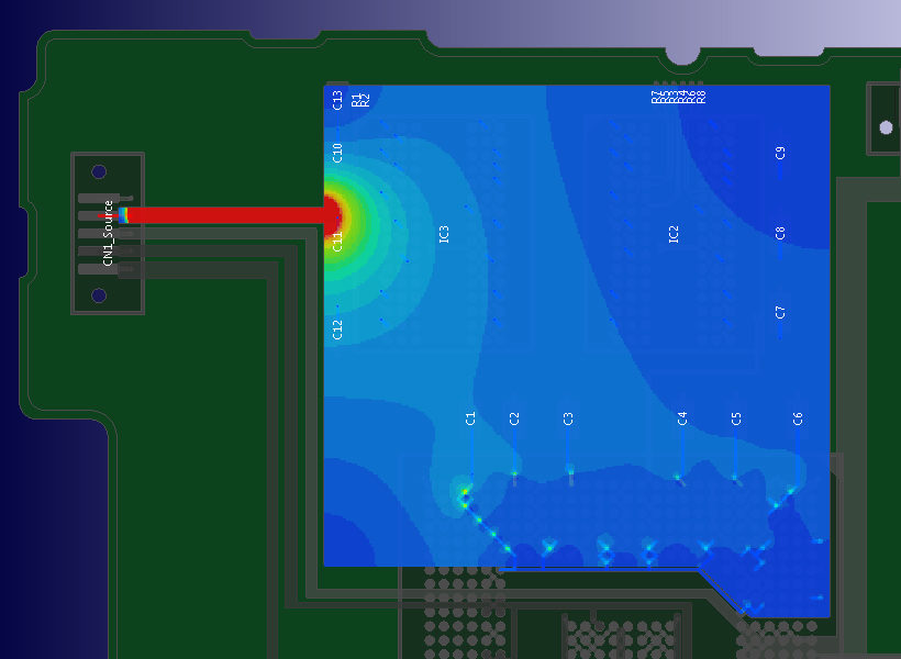
A unified analysis environment for PCB signal and emission performance
EMC Adviser EX provides a focused environment for evaluating electromagnetic compatibility during PCB design. It highlights layout choices that can increase emissions or reduce immunity by examining return-path integrity, plane discontinuities, high-dI/dt nets, and antenna-like routing. The tool surfaces problematic regions, ranks EMC risks, and recommends corrective adjustments while the layout is still flexible. By delivering practical, layout-aware guidance early, EMC Adviser EX helps prevent late compliance failures and strengthens overall EMC robustness.
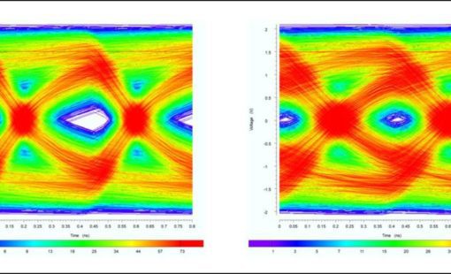
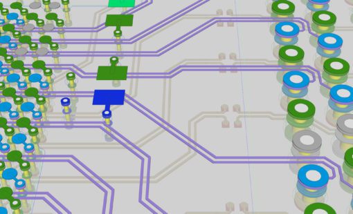
Design Force SI Advance consolidates core signal-integrity analysis into one integrated bundle, giving engineers clearer insight into high-speed behavior as the design evolves. It includes field-solver-based impedance extraction, time- and frequency-domain simulation for reflections and loss, and crosstalk evaluation for early coupling detection. Topology studies support a range of routing strategies, while IBIS-AMI modeling provides realistic analysis of SerDes channels, including jitter and eye performance. Together, these capabilities offer a complete view of SI behavior and support more reliable first-pass results.
Design Force PI/EMI Advance delivers comprehensive power-integrity and EMI analysis directly in the layout environment. Its PI engine evaluates PDN behavior, highlighting voltage drop, transient response, and decoupling effectiveness to ensure stable supply rails. EMI analysis estimates worst-case emissions quickly, accounting for the PCB, attached cables, and heatsinks, and assessing both common-mode and differential-mode radiation. These combined capabilities give early, actionable insight into PDN robustness and electromagnetic behavior, reducing late-stage surprises and improving EMC confidence.
Related Resources
In this Webinar, you will discover how to streamline your PCB design process with CR-8000, and seamlessly integrate prototype testing results using NoiseKen for enhanced accuracy and performance.
In this Webinar, an optimized PCB design flow combining Zuken CR-8000 technology working tightly with stackup optimization capabilities provided by Polar Speedstack ™ will be presented.
Using the example of the analysis of SerDes transmission paths such as PCI Express, SATA or USB3, we explain the methodology of an analysis- and constraint-driven assembly development with CR-8000 Design Force.
In this presentation you will be introduced to the necessary steps in constraining and validation of LPDDR4 on the basis of a real design realized in CR-8000 Design Force right first time.
CR-8000 advances system-level PCB design with significant enhancements in analog simulation, SI analysis, and intelligent layout and routing
In our webinar we will provide an introduction to the challenges of signal integrity and the underlying physical effects. This will provide the basis for practical tips to address the related challenges during PCB design.
Related Blog Posts
Double Data Rate 5 (DDR5) is the next-generation standard for random-access memory (RAM). The new specification promises to bring chips that have much higher performance than the existing DDR4 modules, as well as lower power consumption. Let us show you how you can be first to market with DDR5!
To keep a good high-speed signal quality from driver to receiver on a PCB is not an easy task for designers. One of the most challenging issues is managing the propagation delay and relative time delay mismatches. Let me take you through the process...
What IC designers do to help us route high-speed PCBs
In part 1 of this blog we took a back-to-basics approach and discussed line impedance and its effects in signal integrity. As every electrical conductor comprises capacitance, an inductance, and a frequency-dependent ohmic resistance, and with increasing frequencies, these electrical characteristics will influence and distort the signal.
Impedance and impedance control are some of the oldest and most discussed topics in PCB design. They are especially important in high-speed design related to signal integrity. In this, the first of a two-part blog, we’ll go back to the basics of impedance/impedance control and consider what influences line impedance. In part two, we’ll set about controlling it.
Tips for when routing differential pairs - You can tell when something isn’t as clear as it should be. The same questions come up time and again. You ask three experts and get three different answers. Routing differential pairs can be like that. Why? Because “it depends” - on exactly what signals those pairs are carrying and what kind of PCB you’re creating.