Hydro-Québec power distribution

Hydro-Québec

Hydro-Québec Improves Power Distribution Network Substation Design Productivity by 100%
Menu

Hydro-Québec has simplified the logical and physical design for its power network substations by introducing Zuken’s E3.series electrical engineering software. In addition to accelerating the creation of new projects and modifications in existing designs, the company has also achieved time savings by using templates to duplicate sub-circuits that are repeated many times both within and across projects.

With a total capacity of 36,912 Megawatts produced on 63 generating stations fed by 27 large reservoirs and distributed across 530 substations, Hydro Quebec maintains a comprehensive distribution network across the province of Quebec.  The company’s substations play a key role in controlling power flows. They divide long lines into smaller sections, which helps to minimize any disruption to the continuity of service when a section is not functional, such as during a fault or maintenance period.

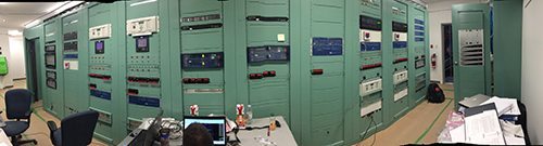
The various components found in a substation include instruments for measuring current and voltage, protective equipment such as circuit breakers for interrupting a line’s current, control devices, and disconnect switches which are used to switch energy from one line to another almost instantaneously when sections are out-of-service.

With new substations that continue to be added to the power distribution network, and modifications to existing substations, substation design is critical for Hydro Quebec’s business continuity. Before adopting Zuken’s E3.series electrical engineering software, Hydro Quebec’s engineers used 2D computer-aided design (CAD) drawing software to produce and maintain well over 1,000 design documents every substation.

In an attempt to implement modifications as quickly as possible, changes were frequently made with scissors and scotch tape on existing drawings. As more and more changes accumulated in the marked-up documents, it became increasingly difficult to understand the change history, and this often led to errors that required time to detect and correct.

The problem with this approach was that the more changes that were made, the harder it became to understand the schematic, which increased the likelihood of errors. “The marked-up drawings made sense to the person who created them, but they were very difficult for others to understand,” says a Hydro Quebec eningeer. “For example, if the owner of the substation later decided that it needed another alarm it was often difficult to determine which cable it should be connected to.”

In addition, each change to the wiring diagram required a corresponding change to the parts list and cable lists. Using a manual update process, it was easy to overlook or enter details incorrectly, leading to inconsistency between drawings, parts lists and cable lists.

To overcome the bottleneck, the company’s engineers benchmarked 10 different software packages. One key advantage of E3.series revealed during the benchmarking process is that it manages both the logical and physical design so that information only needs to be entered once and the software keeps all the different design documents in sync.

The software automatically keeps track of what is connected to what so an engineer can drag a component from one location to another, even from one page to another, and it will automatically update the cables and cross-references across each of the sheets they traverse. When new components are added to a drawing, the software automatically updates the parts list and cable list, eliminating the previous effort for manual updates.

Another key factor in the decision process was the ability to use E3.series in an enterprise installation with multiuser access (E3.enterprise). This enables multiple engineers to work simultaneously on the same design. Multi-disciplined teams of engineers and technicians share the same project and data and any changes carried out by the separate teams propagate through to the other sections of the design, ensuring all data is synchronized and up to date.

Each new substation design contains many circuits that have been used on previous projects. These circuits are therefore often repeated. In the past, engineers and technicians sometimes cut and pasted circuits but the time savings were not great because the designer usually needed to manually reroute the cabling on the wiring diagram, which was typically the most time-consuming part of the process. Hydro-Québec engineers now use E3.series to create template circuit diagrams that specify repetitive circuitry.

These library entries are not simple drawings, but also have the intelligence to know, for example, how many and what type of connectors are contained on each component. Technicians can now drag these templates and drop them into the current drawing and all of the affected cables are automatically moved and properly connected in the new location. The ability of E3.series to manage circuits as templates provides a substantial improvement in productivity and helps avoid errors.


It would have taken a tremendous effort to convert Hydro-Québec’s hundreds of existing substation designs to the new software. Instead, the company designs what they call “brownfield projects” in E3.series. This involves creating virtual circuitry to represent points where the new circuitry connects to existing panels.

The virtual circuitry is often important to the success of the project because key components are often duplicated in brownfield projects so that one station can operate while the other is being upgraded in order to maintain electrical power to customers. These components are incorporated in the virtual circuitry so that instructions can be provided for their management during the commissioning process.

To verify the integrity of their work, Hydro-Québec engineers developed C_Sharp and Visual Basic scripts that run inside E3.series . For example, these scripts look for terminal blocks that have two or more wires connected to them, wires within cables that are not arranged in the normal order, connectors that do not mate properly with one another, assemblies with more wires than pins, etc. so they can be verified manually.

E3.series also simplifies the manual checking process by enabling engineers to simply click on a signal to trace its route through the design. The E3.series database automatically tracks each of the components used in the project so this information can be reported and used by the assembly team. When the checking process has been completed and the design is approved, engineers export the parts list and cable list from the design as an Excel spreadsheet and upload it to the company’s control system.

Results

  • Design productivity doubled with E3.series
  • E3.series manages both logical and physical cable design for consistency
  • Design changes automatically propagate ensuring data is synchronized and up to date
  • E3.series enables multiple engineers to work concurrently on the same design
  • Subcircuit and template usage boosts productivity and eliminates errors.

Download

Download the full case study