
Additive Manufacturing Helps Build Lower Cost Replacement Parts and Tools
It has often been noted that many of the aircraft and other weapons systems used by the armed forces are older than the service men and women operating and maintaining them. While the average age of a U.S. domestic commercial airliner is 11 years, it is not uncommon for aircraft to still be in service at 30 years. Likewise, there are many machines and systems in electric power generation, discrete parts manufacturing, chemical process, oil and gas production and many other industries that have been in continuous operation for several decades or longer.
Production ended long ago on most of these aircraft, weapons systems, machines and equipment so their operators face the challenge of obtaining repair parts and jigs and fixtures needed to keep them operating safely and effectively. In some cases, these parts and tools are available from the original manufacturer but often at an exorbitant cost. In many cases, the original manufacturer no longer exists or no longer provides spare parts or tools. In other cases, the geometry of the aircraft or equipment varies from unit to unit as the design evolved so even though spare parts are available they do not fit.
Reverse engineering
The result is that operators are often faced with the challenge of producing their own spare parts and tools. The traditional approach to reverse engineer replacement parts and tools is to use a coordinate measuring machine (CMM) to capture points one-by-one by touching the probe to the surface of the part. The primary limitation of a CMM is that the operator must manually move the steering system to track each point to be measured.
But to accurately model the geometry of a complex 3D contour, such as is found on many aerospace and other parts, you need millions of points, sometimes many millions, to get the geometry exactly right. There is usually not enough time to take enough points to fully define the geometry, so technicians frequently take a best guess as to the exact surface contours. The inherent inaccuracies of manual measurement methods often require three or four prototype iterations to obtain a good match. So, it often takes months and costs tens or even hundreds of thousands of dollars to produce a single spare part or tool.
Laser scanning for additive manufacturing
A newer approach makes it possible to capture millions of points of geometric data simply by painting the existing equipment with a laser scanner. Laser scanning systems work by projecting a line of laser light onto surfaces while cameras continuously triangulate the changing distance and profile of the laser line as it sweeps along. The laser probe computer translates the video image of the line into 3D coordinates, providing real-time data renderings that give the operator immediate feedback on areas that might have been missed. The large amount of data generated by laser scanners makes it possible to largely automate the process of converting the point cloud of scanned data to a computer aided design (CAD) model.
Laser scanning makes it easier and less expensive to accurately capture the geometry of the existing as-built part. For example, an aircraft manufacturer needed to replace aluminum capping straps that encircle the nacelles that enclose the engines of a commercial jetliner. Accurately sizing the straps and positioning them to the nacelle requires very precise measurements of the complex oblong geometry that changes from the front to the back of the nacelle. Technicians from NVision brought a portable laser scanner to the aircraft and scanned the nacelle with the strap, capturing the nacelle geometry and strap position in a single scan. They then converted the point cloud to a CAD model.
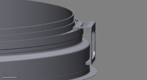
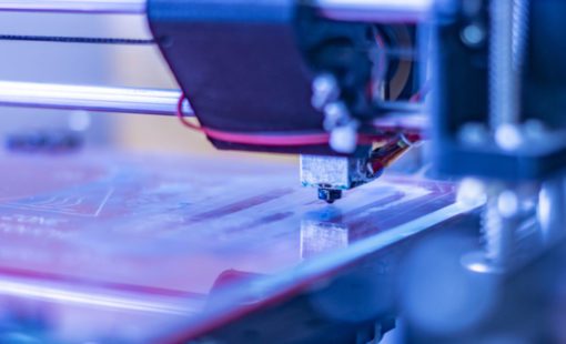
Then the technician used the nacelle geometry to design a tool that fits into a groove on the nacelle and rotates around its circumference to accurately define the position of the straps. NVision produced the tool on a Fused Deposition Modeling (FDM) additive manufacturing system using ABS material.
The original plan was to use the tool produced by additive manufacturing as a prototype to validate the tool design and then build a metal version using conventional manufacturing methods. But the OEM’s repair technicians determined that the tool produced by additive manufacturing worked so well that there was no need for a metal tool. The additive manufacturing tool was built and put into operation in about one week from the inception of the project. If traditional methods had been used to build the tool, it would have taken at least three months and cost about 10 times as much.
- Blog
Executives’ Perspectives on Digital Transformation #6
- Blog
Modern electronic products are no longer built around a single PCB. As systems become faster, denser, and more interconnected, engineering teams are being forced to rethink how they design, verify, and manage complex multi-board products.

- Blog
Executives’ Perspectives on Digital Transformation #5
- Blog
Explore how CR-8000 enhances PCB design with integrated control of impedance and resistance—enabling precise analysis for both high-speed and high-power applications, from signal integrity to power distribution optimization.
Related Content
- Blog
Yes, it is true that even today, so many years after 3D printing started to garner attention and acclaim, rapid prototyping remains the single most common use for 3D printers. 3D printers offer the innovator advantages in the form of shorter turnaround times, improved development secrecy and greater design freedoms. But…it is also true that 3D printing isn’t going to remain as a tool for primarily rapid prototyping for much longer.

- Blog
If you’ve tracked some of the hot topics in engineering over the last year, you’re likely very aware of 3D printing or additive manufacturing. This method lays down successive layers of plastic or metallic material that then fuses them together. Over time, those successive layers add up to make fully formed components...