
The Difference between ECAD and MCAD
Electronics and mechanics are two of the most important disciplines of product development. ECAD and MCAD are the generic names for software solutions that support the virtual design of electronic and mechanical systems in products. The integration of ECAD and MCAD design information and design processes is essential for the development of advanced electromechanical products.
What is ECAD – and what is MCAD?
ECAD stands for Electronic Computer-Aided Design. This term refers to software for the design of electrical and electronic systems. It is used to design printed circuit boards (PCBs), integrated circuits (ICs), and electrical systems. It also includes specialized programs for electrical and fluid engineering. ECAD software is used to create schematics, design and simulate physical layouts, and generate output files for manufacturing.
An alternative term for ECAD is EDA for Electronic Design Automation. The term ECAD is primarily used to distinguish it from mechanical design, which in this context is typically referred to as MCAD. ECAD software is used to create schematics, design and simulate physical layouts, and generate output files for manufacturing.
Mechanical Computer-Aided Design (MCAD) software is used to design, simulate, and document mechanical systems, components, and assemblies. Engineers can create 2D and 3D models, test their behavior under various conditions, and create accurate manufacturing instructions.
Differences between ECAD and MCAD systems
According to the specific needs of each MCAD is primarily 3D-centric, allowing for the visualization and analysis of solids, surfaces, and assemblies, while ECAD is predominantly 2D-based, used for schematics and layouts, though it increasingly incorporates 3D for PCB design and integration with mechanical enclosures.
The libraries used in ECAD systems consequently focus on electrical and functional design attributes such as schematic symbols, wiring rules, and component connectivity, while MCAD libraries prioritize physical and mechanical design with detailed 3D models, material properties, and spatial constraints.
While MCAD and ECAD address distinct aspects of product design—mechanical and electronic/electrical—they increasingly converge in integrated workflows to meet the demands of multidisciplinary projects. Modern product design often necessitates collaboration between MCAD and ECAD to create integrated solutions.
The importance of ECAD MCAD Integration
Integrating ECAD and MCAD design environments is essential for addressing the growing complexity and multidisciplinary nature of modern product development. Products today, especially in industries like consumer electronics, automotive, aerospace, and industrial machinery, often involve tightly coupled mechanical and electronic components. Effective integration ensures that these disciplines work in harmony, minimizing design errors and reducing time to market.
A key reason for integration is mechanical-electrical fit and function. Enclosures, housings, and mechanical structures designed in MCAD must accommodate the size, shape, and thermal requirements of PCBs and electronic components designed in ECAD. Misalignments, such as a PCB not fitting properly in its housing or connectors being inaccessible, can be avoided by synchronizing mechanical and electronic designs early in the process.
Another critical factor is signal and power integrity in physical constraints. Electronics often have specific layout constraints for thermal management, electromagnetic compatibility (EMC), and signal integrity, which must be accounted for in the mechanical design. For instance, heat dissipation requirements for components like power amplifiers or CPUs influence enclosure ventilation or heat sink designs.
Manufacturing alignment is another critical reason. ECAD and MCAD collaboration ensures that the design output meets both electronic and mechanical manufacturing requirements. For example, an enclosure with tight tolerances for PCB mounting holes must align with the board layout to avoid assembly issues.
A key aspect of ECAD MCAD integration is the need to integrated with Product Lifecycle Management (PLM) and Product Data Management (PDM) systems to enable the efficient management of design data throughout the product development process.
The Right ECAD PCB Software for a Streamlined Workflow
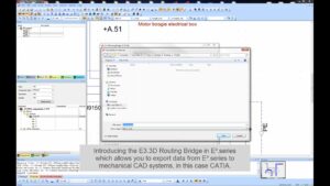
Zuken’s CR-8000 and E3.series electronic and electrical design suites facilitate seamless ECAD/MCAD integration, ensuring effective collaboration between electrical, electronic, and mechanical design teams.
CR-8000 provides 3D visualization, bidirectional data exchange via standard formats like STEP and IPC-2581, and centralized library management to synchronize PCB layouts, wiring, and mechanical enclosures. It also integrates thermal and structural analysis, allowing cross-disciplinary teams to validate designs early, reducing errors and iterations.


- Blog
Modern electronic products are no longer built around a single PCB. As systems become faster, denser, and more interconnected, engineering teams are being forced to rethink how they design, verify, and manage complex multi-board products.
- Blog
Explore how CR-8000 enhances PCB design with integrated control of impedance and resistance—enabling precise analysis for both high-speed and high-power applications, from signal integrity to power distribution optimization.

- Blog

- Blog
AI in PCB design is increasingly seen as a game-changer, with some predicting it could soon replace entire layout teams—but this view risks overlooking both the current limits of AI and the critical expertise engineering demands. At DesignCon 2025, experts from emphasized that AI's real value lies in complementing human judgment, not replacing it. Read more on our blog.

- Products
E3.series is a true concurrent electrical engineering environment supporting advanced requirements for electrical documentation, cabinet and wire harness design and manufacturing outputs.

- Products
CR-8000 is a System-Level PCB & IC Package Design software including 3D Multi-board, Analysis and MCAD Integration