
Low voltage or over current, which are you?
Changing standard components in an electrical system is a common task but it entails a number of time-consuming checks that engineers must carry out to avoid trouble. For example, replacing a windscreen wiper motor may seem like a simple task, but what if the new motor is more powerful?
It could be a simple case of uprating the fuse size from a 15-amp fuse to a 20-amp fuse. But will the current wiring size be ok? Maybe the 1.5mmSQ cable is fine, but how long is the wire? Should the wire be upgraded to 2.0mmSQ cable or even 2.5mmSQ?
- If the fuse is too small, then a fuse that blows daily will be a constant issue, which will undoubtedly lead to unhappy operators.
- If the wire is too small, it could cause a voltage drop issue and result in the motor not working correctly. Even worse, the wire is too small and could cause a thermal event – a recipe for disaster!
To ensure these issues don’t occur, engineers have to do lots of time-consuming calculations, checks, and re-checks – and if they’re not done correctly, they can easily result in errors that are costly to fix in production or may even lead to malfunction in the field.
E3.series solves these potential issues with its intelligent component-based parts library, optional Component Cloud for E3.series, and automated circuit simulation.
Components in the database can be created to contain electrical functional details for example:
- maximum voltage
- minimum voltage
- nominal voltage
- power, and resistance
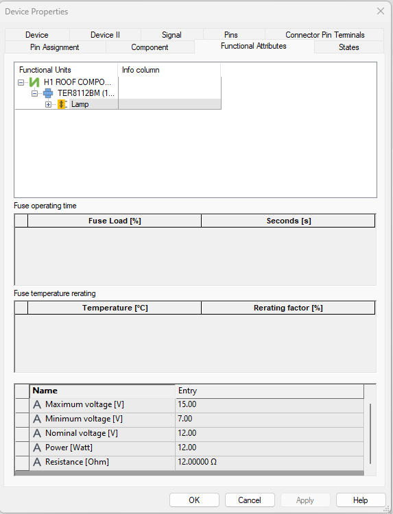
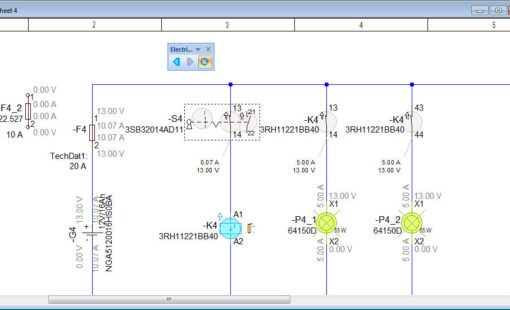
When these components are added to a design, E3.eCheck can simulate the system voltage and display component status information.
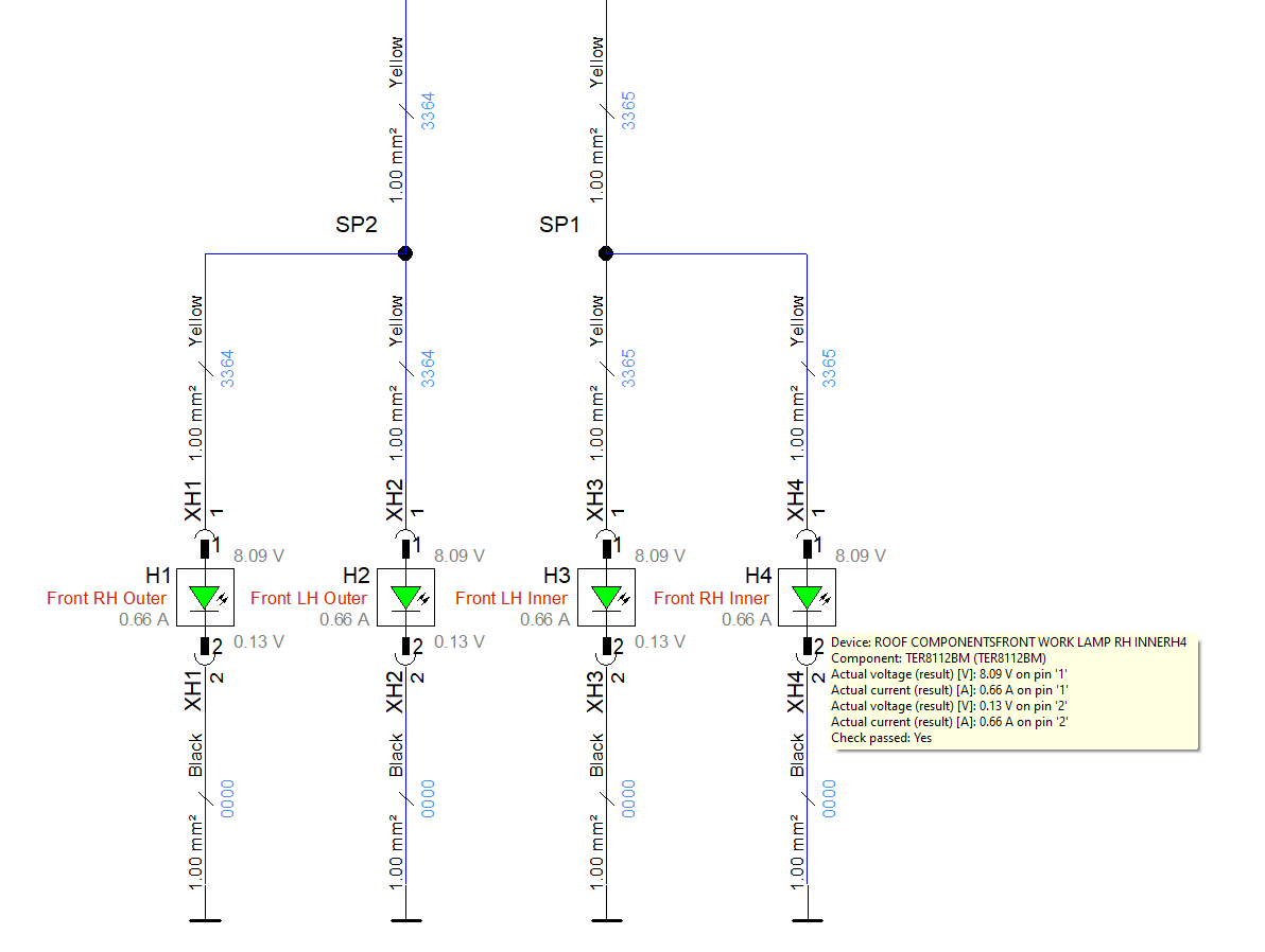
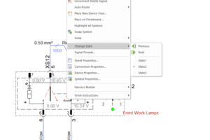
Colors and movements of components can also be simulated to replicate component states to allow quick and easy viewing of the system state. Lamps can change color to indicate on / off, switches can change position, etc.
Multiple states can be created within the component to simulate different functions. For example, a switch can have three states, off, position 1, and position 2. This gives you the ability to change the position of a switch and easily test different functionalities.
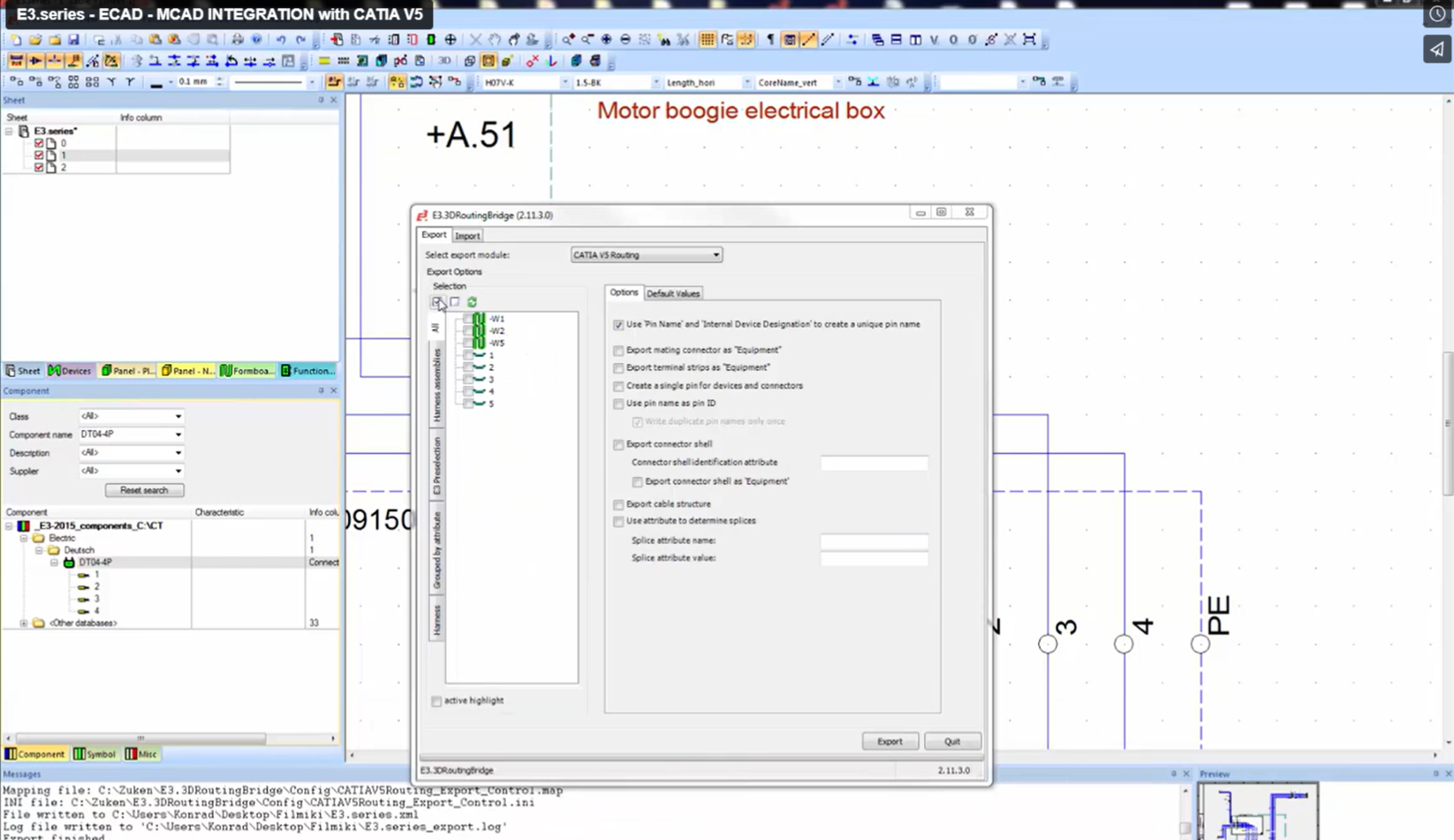
E3.echeck can also use wire lengths to calculate the voltage drop. Design engineers can physically modify the length to replicate the new requirement or use E3.RoutingBridge to import the wire lengths directly from the MCAD design.
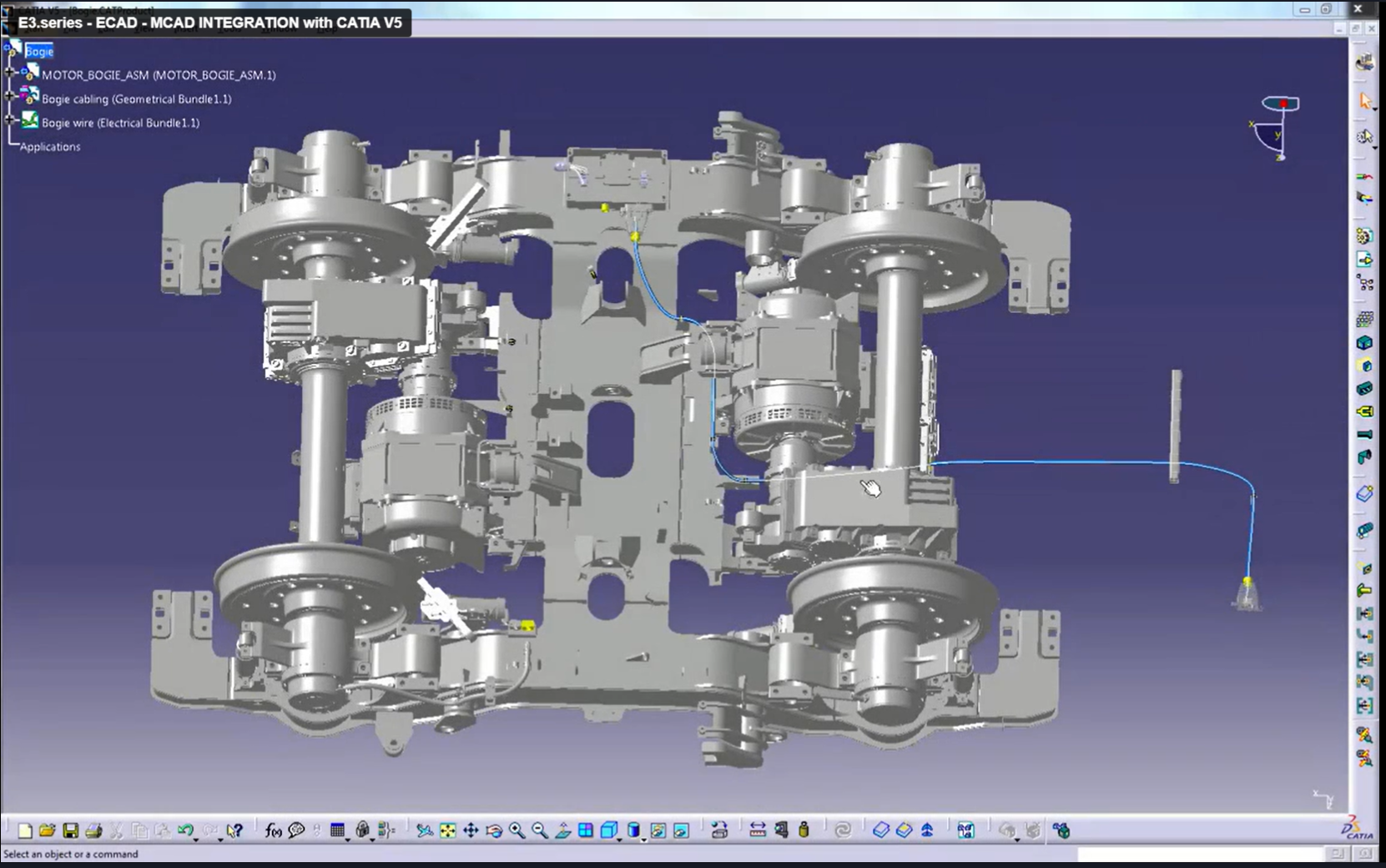
This method means that devices can be placed or moved in the MCAD world, wire routing can be updated, and then the new information can be seamlessly imported back into E3.schematic and verified using E3.eCheck, to simulate the new system to check the effect of the changes.
Using E3.eCheck in conjunction with E3.schematics’ intelligent component-based parts library engineers across the globe can create or replace components in a design, and verify that items such as terminals and seals are available and that the selected wires, fuses, etc. are correct. The simulation and design rule checks alert engineers to potential problems long before the design is ready for manufacturing.


- Blog
Build accurate dynamic cables in E3.series by defining cores, shields, and twisted pairs so schematics, reports, and formboard outputs stay consistent.

- Blog
E3.series automation is entering a new era as Microsoft phases out VBS. With the official Python package, Zuken offers a modern, future-proof way to automate E3.series while preserving all familiar capabilities.
- Blog
Use Fields in E3.series to stop splitting designs across multiple pages, keep device inheritance correct, and generate clean reports when multiple functions share one sheet.
- Blog
Use Fields in E3.series to stop splitting designs across multiple pages, keep device inheritance correct, and generate clean reports when multiple functions share one sheet.
Related Content

- Webinar
Design errors due to tolerance violations often lead to the expensive recall of vehicles and equipment. Detection and correction of these errors early in the design chain can eliminate downstream headaches.
- Products
E3.eCheck is an extension to E3.series that enables users to functionally analyze their electrical schematic circuits and check designs for fuse and wire sizing errors.

- Case Study
KRONE, a major brand in the agricultural machinery market, implemented an interdisciplinary product development process. Using Zuken’s E3.series, KRONE linked ECAD, MCAD and ERP to develop an integrated digital engineering and sourcing process, achieving sizable benefits for both sourcing and service. With an integral representation of mechanical and electrical product information, KRONE was able to make solid progress in implementing its major business optimization strategies: Industry 4.0 and Farming 4.0.