
Tech Tip: Automatic Schematic Connections With Arrange Logical Nets in CR-8000
Engineers draw schematics to create circuits, not extra drafting work. But turning a circuit’s logic into a diagram that everyone can understand often requires additional effort. Automatic schematic connections reduce that effort, so the engineer’s time can go toward circuit design rather than graphic design.
CR-8000 Design Gateway includes tools that support this more focused approach. This tech tip explores why schematic readability matters and demonstrates a faster way to create, name, and revise connections.
Why Engineers Use CAD Software to Create PCB Schematics
A schematic shows the connections between components in an electronic circuit. Engineers use advanced CAD (computer-aided design) software to create these diagrams to capture more than symbols and lines. In software like CR-8000, schematics carry intelligence that supports the work that follows.
- Component and connection data feeds into PCB layout, where designers place parts and create copper paths
- Parts data supports bills of materials and automated manufacturing processes
- Built-in checks help engineers find problems before the design moves downstream.
With CAD software, the schematic becomes more than a picture; it becomes the source of truth to build the PCB circuit.
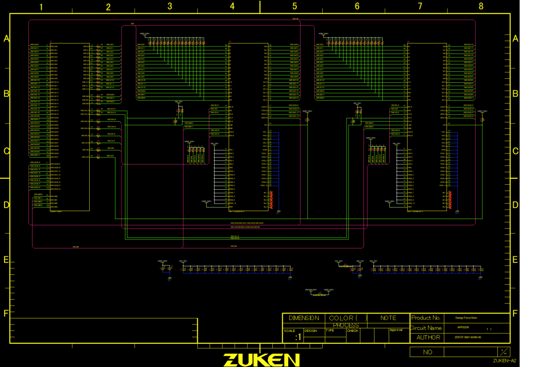
Schematics Are for People, Not the Software
Engineers use schematics to understand a circuit and check that it will work as intended. A clear diagram helps them follow signals, review design decisions, and explain the circuit to others.
The software uses the underlying data to support downstream processes such as component placement and manufacturing. Hypothetically, an engineer could import parts and connection tables to define which components exist and which pins connect. The software does not need a neatly arranged schematic to understand those relationships.
People do. Well-organized symbols and clear connection paths make a circuit easier to follow. Crowded lines, unnecessary bends, and confusing crossovers make it harder to read, even when the connectivity is correct. Making a schematic look good serves a practical purpose: helping the people who use it understand and evaluate the design.
Separate Connectivity from Visualization using Automatic Schematic Connections
When engineers draw connections on a schematic, they focus on defining the circuit’s logical connectivity. But as they draw each line, they’re also making a second set of decisions: how those connections will look.
Engineers specialize in designing circuits, not arranging lines on a page. Making every connection easy to follow takes a different kind of effort. Time spent adjusting lines is time away from the circuit itself.
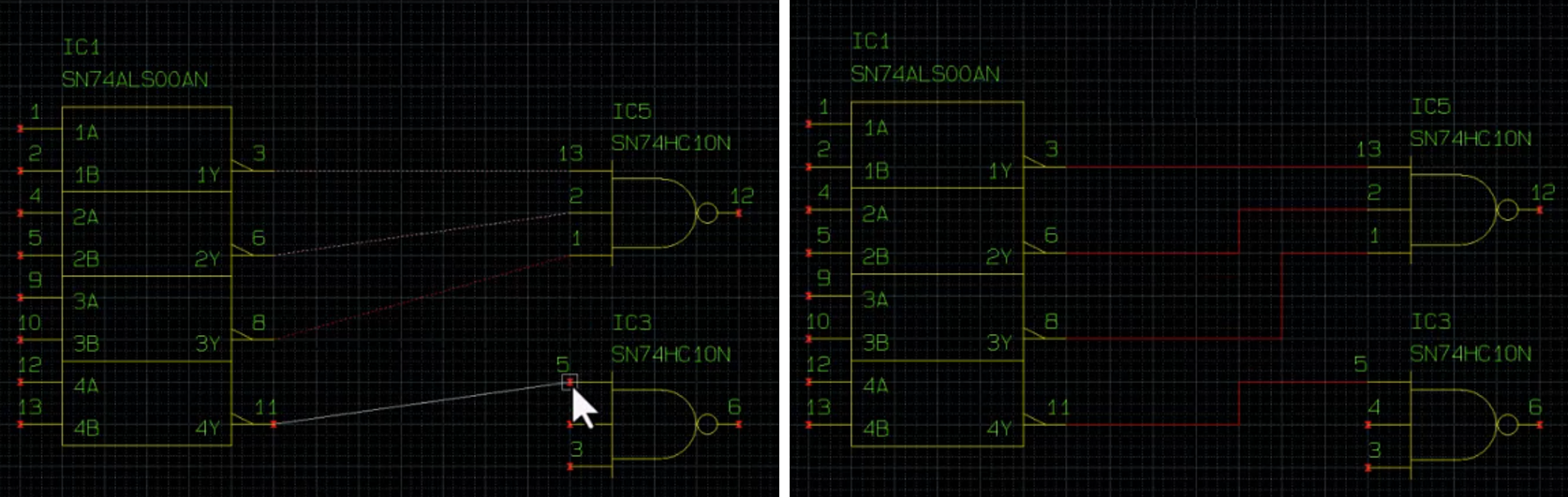
With automatic schematic connections, engineers define the logical connectivity and let the CAD software draw the connection lines. They can focus on what needs to connect, let the software handle the initial arrangement, and refine the resulting diagram as needed.
How to Create and Manipulate Automatic Schematic Connections in CR-8000
CR-8000 Design Gateway puts this approach into practice with Arrange Logical Nets. Working in Logical Net mode, engineers define connections between pins, then use the software to generate net figures, apply consistent naming, and redraw connections as needed.
Automatically draw connection lines
Once in Logical Net mode, the engineer defines connections between pins in the Design Editor. The connections appear as a rat’s nest of dotted lines, but it’s only a temporary placeholder. After defining a set of logical connections, the engineer runs the Arrange Logical Nets command to generate automatic schematic connections.
Automated net naming
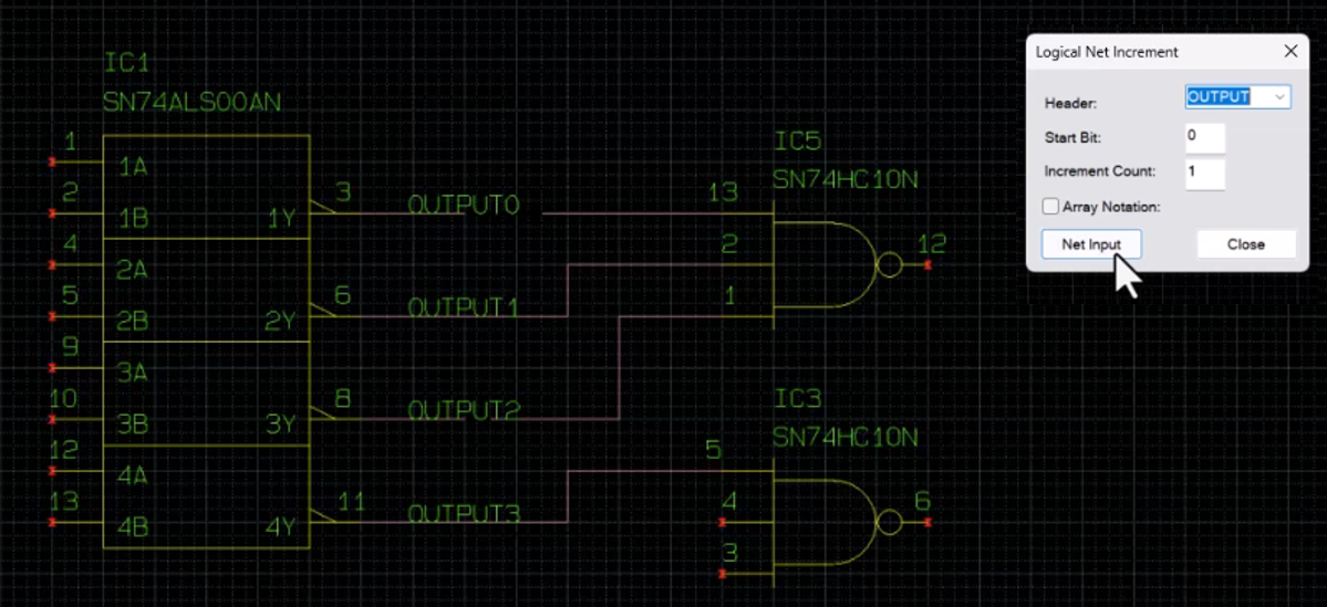
Logical Net Increment assigns names as engineers create connections. A name prefix, start bit, and increment count establish the naming sequence, reducing the need to enter each net name individually. Once the naming sequence is set, the engineer selects the connection lines, and the software assigns the net names automatically.
Deleting and redrawing nets
Delete Net Figure allows engineers to remove connection lines without deleting the underlying logical connectivity. The connections return to a rat’s nest of dotted lines, allowing the engineer to run Arrange Logical Nets again and generate new automatic schematic connections.
Watch Automatic Schematic Connections in Action
The following video demonstrates how to define logical connectivity, generate connection lines with Arrange Logical Nets, apply automatic net names, and delete net figures for redrawing.
Who Benefits from Automatic Schematic Connections
Automatic schematic connections benefit creators and teams that use their diagrams.
People who create schematics
- Electrical engineers define connectivity while spending less time arranging lines.
- Circuit and CAD designers create and revise readable diagrams faster.
People who use schematics
- Design reviewers and PCB layout engineers interpret circuit intent.
- Test and service teams trace connections during hardware validation and troubleshooting.
Summary and additional resources
Clear schematics help engineers and other stakeholders understand, review, and troubleshoot circuit designs. However, creating that clarity can require significant time arranging connection lines by hand.
Arrange Logical Nets separates logical connectivity from graphical presentation. Engineers define which pins connect, and CR-8000 Design Gateway generates the connection lines. Automatic net naming and the ability to delete and redraw net figures further simplify schematic creation and revision.
Learn how CR-8000 supports circuit engineering from schematic design through PCB layout and manufacturing.
- Vist CR-8000 product page to learn more about PCB circuit design
- Read this blog on system-level PCB design for multi-board products
- Learn what’s new in CR-8000 2026

-
Applications Engineer

- Blog

- Blog
- Blog
- Blog
Related Products and Resources
- Products

- Blog
- Blog

- Blog