Yanmar Advances Construction Equipment Electrification with E3.series
As construction equipment manufacturers accelerate the transition toward electrification, they face new engineering challenges that extend far beyond replacing a diesel engine with a battery. Electrical architectures become more complex, wiring systems require careful planning, and new design constraints must be addressed early in development.
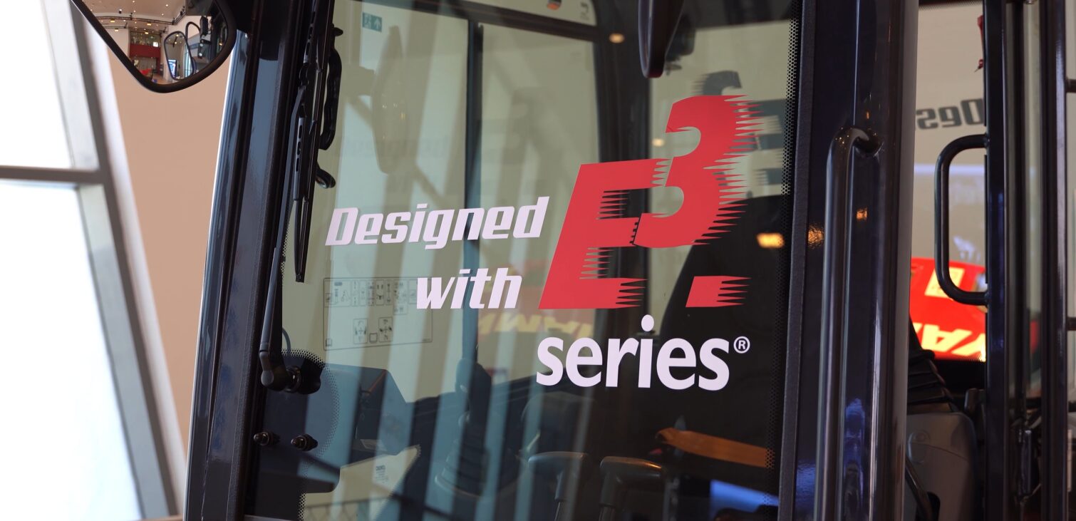
At Zuken Innovation World 2026, Antoine from Yanmar showed the company’s SV17e, a fully electric compact excavator, and explained how Yanmar is using E3.series to support the development of its next generation of construction machinery.
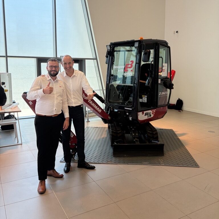
A Fully Electric Compact Excavator
The Yanmar SV17e is a 1.7-ton compact excavator designed specifically for construction and public works applications. Although the machine continues to use hydraulic actuation, it produces zero carbon emissions during operation thanks to its fully electric powertrain.
According to Yanmar, the combination of compact dimensions, high power and quiet operation makes the machine well suited for environments where traditional diesel equipment faces increasing restrictions.
Meeting New Requirements on Construction Sites
Electrification addresses several practical challenges that are becoming more important across the construction industry.
One of the most significant is noise reduction. Quieter machines make it possible to work during nighttime hours or in densely populated urban environments where noise regulations are stricter.
Because the excavator produces no exhaust emissions, it can also be used indoors or in enclosed spaces where diesel-powered equipment would not be suitable.
While acquisition cost remains a consideration for customers, Yanmar noted that government incentive programs, including support through France’s ADEME, are helping encourage investment in electric construction equipment, similar to incentives available in the passenger vehicle market.
Developing the Electrical Architecture with E3.series
The transition from diesel to electric machines introduces additional engineering complexity. Higher electrical requirements, more sophisticated wiring systems and new integration challenges all need to be addressed during development.
Yanmar explained that the entire electrical architecture of the SV17e was developed using E3.series. During development, E3.series enabled the engineering team to:
- Plan wiring harness routing early in the design process.
- Develop the machine’s complete electrical wiring logic.
- Integrate the additional constraints introduced by electrification during the early design phases.
- Support both the electrical and hydraulic aspects of the machine design.
According to Yanmar, addressing these factors earlier in development helped the team better anticipate implementation challenges before production.
A Commercially Available Electric Machine
The SV17e has already been on the market for approximately 18 months. Yanmar reports that customer feedback has been particularly positive regarding the machine’s performance, with users often surprised by the level of power delivered by the electric drivetrain. While purchase cost continues to be a topic of discussion, the company says customer satisfaction with the machine’s capabilities has been strong.
The SV17e is also part of a broader portfolio of compact electric machines, with additional products currently under development as Yanmar continues expanding its electrification strategy.
Supporting the Next Generation of Construction Equipment
As construction equipment evolves toward quieter, cleaner and increasingly electrified machines, engineering teams must manage greater electrical complexity while maintaining reliability and performance.
For Yanmar, E3.series provided a platform for developing the machine’s electrical architecture, planning wiring systems and integrating the additional design constraints associated with electrification early in the development process.

- Blog
- Blog
Discover how Alpine Tech is applying Formula 1 engineering expertise to help customers accelerate product development with rapid prototyping and E3.series.
- Blog
Executives’ Perspectives on Digital Transformation #6
- Blog
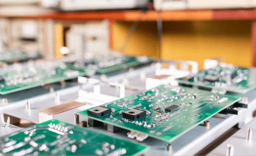
Modern electronic products are no longer built around a single PCB. As systems become faster, denser, and more interconnected, engineering teams are being forced to rethink how they design, verify, and manage complex multi-board products.