High‑Speed Serial Link Design: The TWO Things That Make Links Work (and Fail)
Guest author: Donald Telian (SI Guys) – Signal‑integrity veteran, IBIS co‑founder, and author of Signal Integrity, In Practice.
Why Do Serial Links Work?
In this talk, Donald Telian explains that the very two things that make links work are also the things that make them fail – when they’re not done right. High-speed links work electrically when you:
- Deliver ~10 mV accuracy from the transmitter (Tx) to the receiver (Rx)
- Properly equalize at the system level
This blog post outlines the primary technical requirements for getting both right. With tens of thousands of links in production, Donald has found serial technology to be surprisingly robust: when these basics are nailed, the links work right the first time. But when engineers overlook them, that’s when his phone rings.
These fundamentals are also central to a conversation we’ll be recording with Donald and Ralf Brüning (Zuken) – and we’d love your input.
Post your question or topic in the comments below, and it could be part of the discussion released on September 15, 2025.
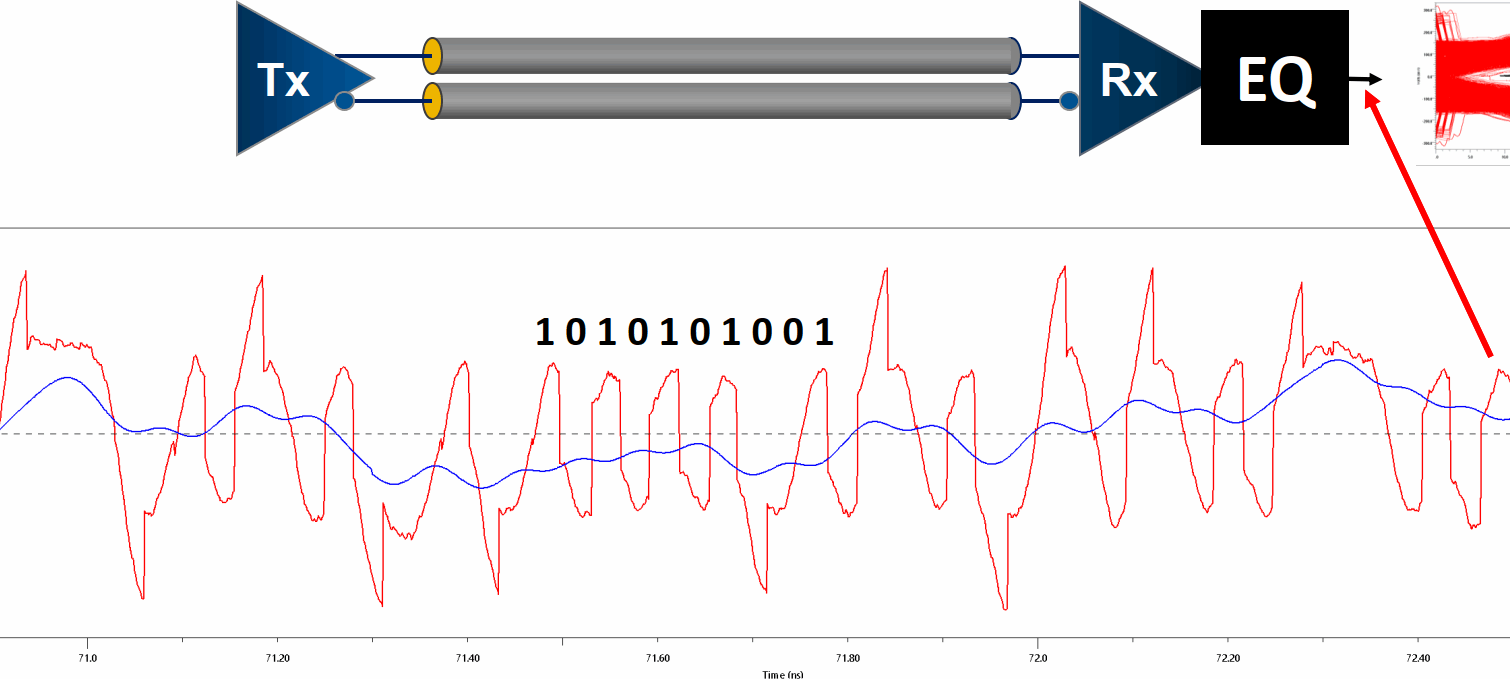
Every new product – from automotive radar units to 112 Gb Ethernet switch cards – now relies on high-speed serial link design. These links carry data at 7 – 70 Gbps over just a handful of differential pairs, but they also push engineers into a world where chip-to-chip channels behave like RF networks, not DC traces. A healthy 1 V swing at the transmitter can shrink to barely 10 mV at the receiver. Designing within that narrow millivolt window is possible, but only if you master the two fundamentals above.
Watch the Full Podcast
Before we dive deeper, hear Donald explain these two make-or-break fundamentals in a 30-minute SI Guys podcast. You’ll get practical examples from 7 – 70 Gbps designs, the common mistakes that sink links, and real-world fixes you can apply right away.
The TWO Fundamentals Behind Reliable Links
Everything in this blog comes back to two design fundamentals. If you can consistently get these right, your links are far more likely to work the first time.
1) Deliver ~10 mV Accuracy to the Receiver
At today’s speeds, every millivolt counts. If too much of your signal is lost between the transmitter and receiver, even the best equalization can’t recover it. Think of the channel – traces, vias, connectors – as a tax office that charges a “millivolt fee” at every discontinuity and loss contributor. If your account drops to less than 10 mV in total, the receiver runs out of margin.
Breakout vias, connector pads, and stubby through-vias are the usual culprits. A time-domain reflectometer (TDR) trace showing swings larger than ±10 Ω around the target impedance (e.g., 85 Ω) flags trouble long before lab time.
2) Apply the Right System‑Level Equalization (EQ)
Modern serializer/deserializer (SerDes) devices include digital signal processing (DSP) engines that perform serial link equalization techniques such as:
- CTLE (Continuous-Time Linear Equalization) – Think of it like turning up the treble to restore lost high-frequency detail.
- FFE (Feed-Forward Equalization) – Shapes the signal at the transmitter to compensate for expected channel loss.
- DFE (Decision-Feedback Equalization) – Removes distortion caused by previous bits once the signal is received.
Done right, EQ turns that tiny 10 mV waveform back into something your receiver can decode reliably. Done wrong, it magnifies noise and jitter.
A good starting point:
- Turn off all Tx EQ at first
- Let the Rx’s adaptive EQ do its job
- Only add the minimal Tx taps the Rx can’t generate itself
Signal Integrity Challenges at Multi‑Gbps
Once you lose sight of the two fundamentals, three major troublemakers tend to appear:
1) Equalization that’s out of tune – Auto settings can overshoot or undershoot the sweet spot. It’s not too difficult to learn how to tune EQ once a couple basics are understood – particularly the channel’s pulse response. A pulse response is the channel’s identity (fingerprint), and tells you how to set your EQ mathematically.
2) Little bumps in the copper – Every via, capacitor pad, or stub acts like a speed bump that steals a few precious millivolts. Donald lists eight ways to fix these, but nine times out of ten the best answer is to remove the bump or reshape it to match the surrounding impedance.
3) Crosstalk between traces – Often caused by gaps in your ground or power planes. As a rule, leave at least 30 mil spacing between high-speed pairs and never run a sensitive trace under a large plane void. Even a 6 mil gap can couple about 1 mV for every mil of overlap – which is a huge hit when your entire budget is only 10 mV.
Transmitter vs. Receiver Equalization (High‑Speed Links)
Equalization comes in two main flavors:
- Tx equalization – Pre-/de-emphasis boosts or attenuates certain frequencies before the signal leaves the transmitter
- Rx equalization – CTLE restores high-frequency content, and DFE cancels inter-symbol interference after the signal is received
Balancing the two:
| Step | Action | Why |
|---|---|---|
| 1 | Disable Tx EQ | Reveals what the Rx can already recover. |
| 2 | Let Rx adaptive EQ converge | Modern silicon handles most post-cursor loss automatically |
| 3 | Add minimal Tx pre‑cursor taps | Most Rx can’t EQ pre-cursor ISI – a small Tx boost can open the eye |
| 4 | Program Firmware | Correct EQ settings are useless until they make it into component register sets. |
Following these steps avoids the classic “EQ wars,” where Tx and Rx over-correct each other into non-optimal performance, wasted power, and even link failure.
Design‑Phase Checklist
A quick five-step sanity check before sign-off to confirm your board still meets the 10 mV accuracy goal and EQ can do its job:
- Manage or remove discontinuities. Model every via, connector, and pad transition, and to match your end-to-end impedances. TDR plots reveal both discontinuity magnitude and position.
- Fingerprint the channel early. The pulse response, easily produced by simulation will reveal if you’re fighting significant loss or sharp reflections and will tell you how to EQ your link.
- Backdrill or shorten stubs. A 100 mil stub at 28 Gbps can kill your signal and remove all eye height. Backdrill, or use blind/buried vias.
- Police plane cut‑outs. Voids in planes invite crosstalk. Keep ground continuous under high-speed pairs, and use stitching vias to maintain return paths.
- Optimize EQ. Program every Tx/Rx EQ register sets with values appropriate for your link’s components and behavior. Saves days when new silicon arrives.
What We’ve Learned
High-speed serial links live on millivolt margins. Keep the 10 mV-at-Rx budget in sight, fix physical discontinuities early, and let system-level equalization do only what silicon can. Fingerprinting the channel, removing stubs, and programming EQ settings turn trial-and-error into a repeatable process for open eyes and low BER.
Get these right, and you can push data rates past 28 Gbps – and sleep at night.
Ready to Level Up?
- Live SI Guys Training – Munich, 29 and 30 October 2025: A two-day, vendor-neutral deep dive into everything above. Join us to learn Gen2 SI and succeed with Signal Integrity, in Practice. Register here
- Coming September 15, 2025: A recorded discussion where Donald trades design tips and war stories with Ralf Brüning (Zuken) about the latest trends in high‑speed SI.
We want your questions for Donald and Ralf!
Post it in the comments below – we’ll be reviewing submissions to help shape their conversation. This is your chance to influence what two of the industry’s leading SI experts discuss. And don’t forget to subscribe for updates so you’re the first to know when the discussion is released.

-
Author/Signal Integrity Specialist - SIGuys.com

Donald Telian has pioneered Signal Integrity for more than 40 years. For the last 20 years he has been a Consultant, focused on designing serial links into products from flash drives to switches with thousands of links. He has invented various SI concepts, tools, and quirks engineers use everyday to get their jobs done. He is widely known as the originator of IBIS, PCI, and the author of “Signal Integrity, In Practice” – a new book and LIVE 2-day class Gen2 SI that cuts through the noise to explain how to “do” SI when confronted with the data rates of today. Learn more at siguys.com.

- Blog
- Blog
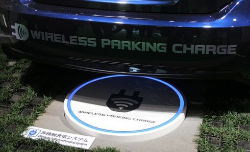
Wireless Power Transfer (WPT) is replacing cables and wires in consumer electronics, electric vehicles (EVs), and healthcare. Zuken offers a suite of solutions that help engineers design, simulate, and validate WPT systems. Learn more.

- Blog
EMC problems are often responsible for re-design cycles in PCB design practice. Due to ever shorter innovation cycles of for example cell phones or IoT applications, such as fitness trackers or smartwatches, and many other electronic products, these time-consuming re-design cycles should be avoided under all circumstances.

- Blog
In part 1 of this blog we took a back-to-basics approach and discussed line impedance and its effects in signal integrity. As every electrical conductor comprises capacitance, an inductance, and a frequency-dependent ohmic resistance, and with increasing frequencies, these electrical characteristics will influence and distort the signal.