
Tech Tip: Termination Resistor Placement with Pin Pair Constraints in CR-8000
Termination resistors improve signal quality by reducing reflections and impedance discontinuities. Their effectiveness depends not only on resistance value, but also on location relative to the driver. CR-8000 enforces termination resistor placement constraints to prevent excessive electrical distance and protect signal integrity.
Why Termination Resistors Are Used in PCB Design Implementation
When signals travel along PCB transmission lines, impedance mismatches cause reflections. These reflections distort the waveform, introduce ringing, and can lead to unreliable logic levels. Termination resistors are used to control these effects and maintain signal integrity.
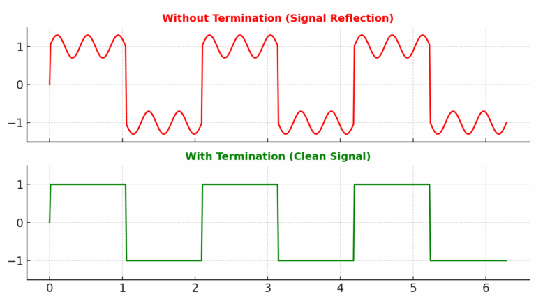
Proper termination improves impedance matching between the driver, the interconnect, and the load. By aligning these impedances, signal distortion is minimized and overall waveform quality is preserved.
Establishing Proper Termination Resistor Placement
Determining the proper placement of termination resistors requires more than selecting the correct resistance value. The distance between the driver and the resistor directly affects how effectively reflections are controlled. If the resistor is placed too far from the source, the intended impedance control can be compromised.
In many design environments, placement guidance is communicated through notes, emails, or verbal instructions. Over time, this information can be overlooked or misinterpreted. Without a formal mechanism to define maximum allowable distance, termination effectiveness can vary from one layout revision to the next.
Pin Pair Constraints to Enforce Termination Resistor Placement
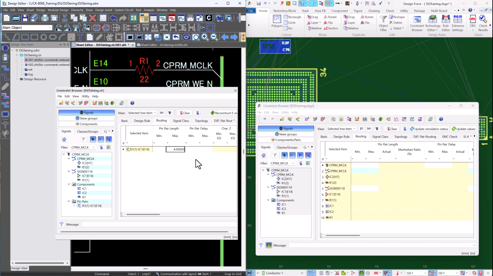
Pin Pair constraints communicate placement intent directly from the schematic to PCB layout. Instead of relying on documentation or memory, electrical requirements are embedded directly in the design database.
For source termination resistors, the Max Pin Pair Length constraint is applied between the driver pin and the termination resistor pin. This defines the maximum allowable distance between the source and the resistor, transferring placement requirements automatically to layout.
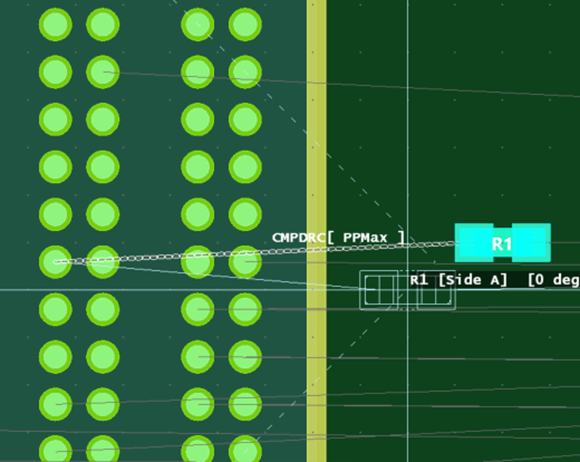
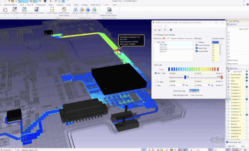
When enabled, the layout environment displays a visual placement boundary that clearly indicates the compliant region. If the resistor is placed outside this boundary, it becomes immediately apparent that the component must be moved closer to the driver. This approach provides immediate feedback and prevents ineffective termination distance.
How Pin Pair Constraints Work in CR-8000
- Identify the nets that require termination resistors to improve signal integrity.
- In Design Editor, use the Constraint Browser to create Pin Pairs for the driver and termination resistor pins.
- Apply a Max Pin Pair Length constraint to define the allowable electrical distance.
- In Design Force, enable the appropriate Design Rule Check to monitor maximum track length compliance.
- During layout, place the termination resistor within the visual boundary defined by the constraint.
- Perform a placement audit to confirm the resistor remains within the compliant region.
For a detailed, step-by-step walkthrough of this workflow in CR-8000, watch the video demonstration below.
Who Benefits from Constraint-Driven Termination Placement
Lead Hardware Designers
Why it helps: Lead hardware designers define the electrical requirements for termination, including allowable distance from the driver. Pin Pair constraints ensure those requirements are formally embedded in the design.
Benefit: Placement intent is enforced automatically in layout. This preserves signal integrity objectives and prevents performance degradation caused by excessive electrical distance.
PCB Layout Engineers
Why it helps: Pin Pair constraints define a clear, compliant placement region directly in the layout environment.
Benefit: Layout engineers can place termination resistors with confidence, relying on enforceable design rules instead of informal guidance. This reduces interpretation errors and improves first-pass layout success.
Next Steps: Strengthen Signal Integrity with CR-8000
Pin Pair constraints in CR-8000 enforce termination resistor placement by controlling electrical distance directly within the design environment.
More broadly, CR-8000 embeds signal integrity requirements into enforceable design rules that connect schematic intent to PCB layout. Constraint-driven controls help teams preserve electrical performance, reduce interpretation errors, and maintain design integrity across revisions and reuse.
Learn more about how CR-8000
- Read about constraint-driven PCB design
- Read how to implement signal integrity screening
- Visit the CR-8000 product page.
- Sierra circuits termination resistor

-
Applications Engineer


- Blog
- Blog

- Blog
- Blog
Related Products and Resources
- Blog

- Press Release
- Products
CR-8000 Release 2025 brings enhanced simulation workflows, strengthened multi-board 3D co-design, expanded AI-assisted routing, and tighter PLM synchronization
- Blog