What's New in CR-8000 2019
Highlights of the 2019 release
Automation and Control
Release 2019 CR-8000, Zuken’s enterprise-level electronic design environment, has received enhancements and extensions to support engineering and layout productivity through enhanced frontloading, extended control of automatic functionality for layout and routing, and active avoidance of design errors through design rule checks.

Constraint Browser
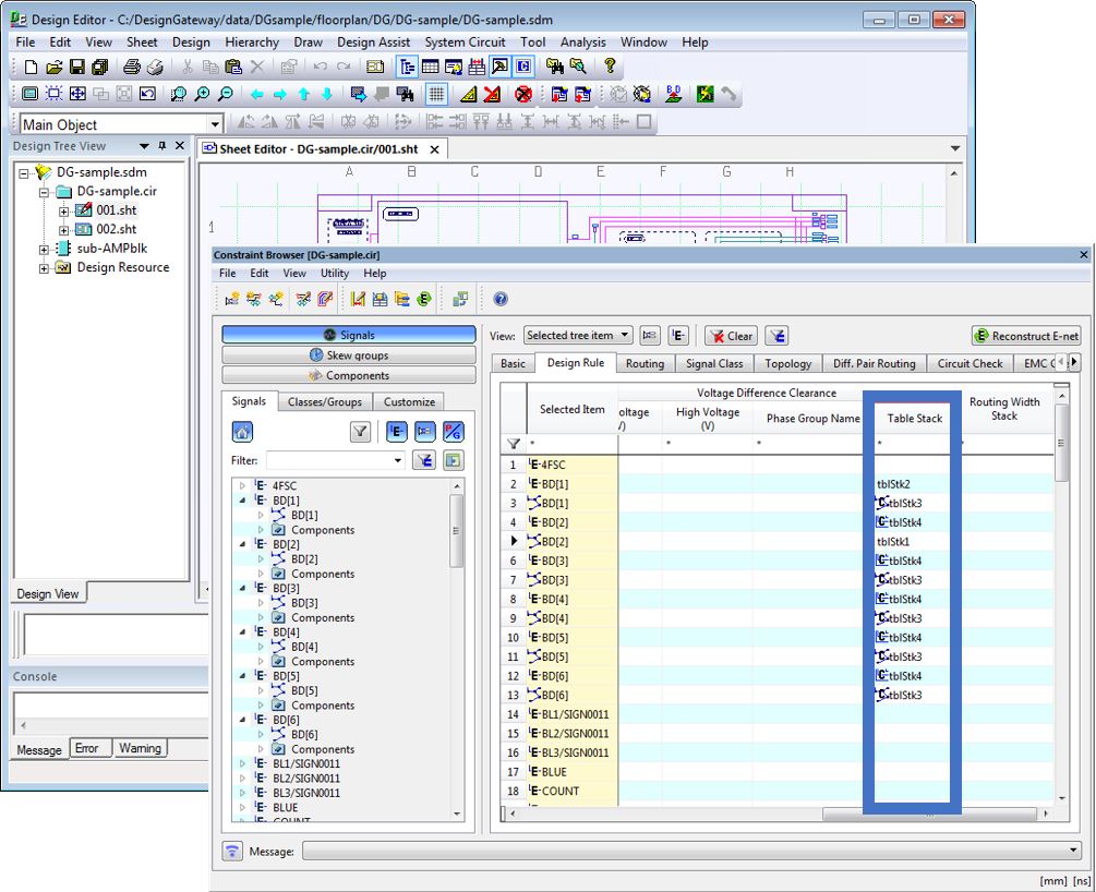
- The Constraint Browsers of Design Force and Design Gateway have been harmonized. It is now possible to access component and component pin properties from the Design Gateway Constraint Browser.
- The voltage difference clearance table stack can be predefined in Design Gateway. The information can be transferred to Design Force using Forward Annotation.
Check and verification
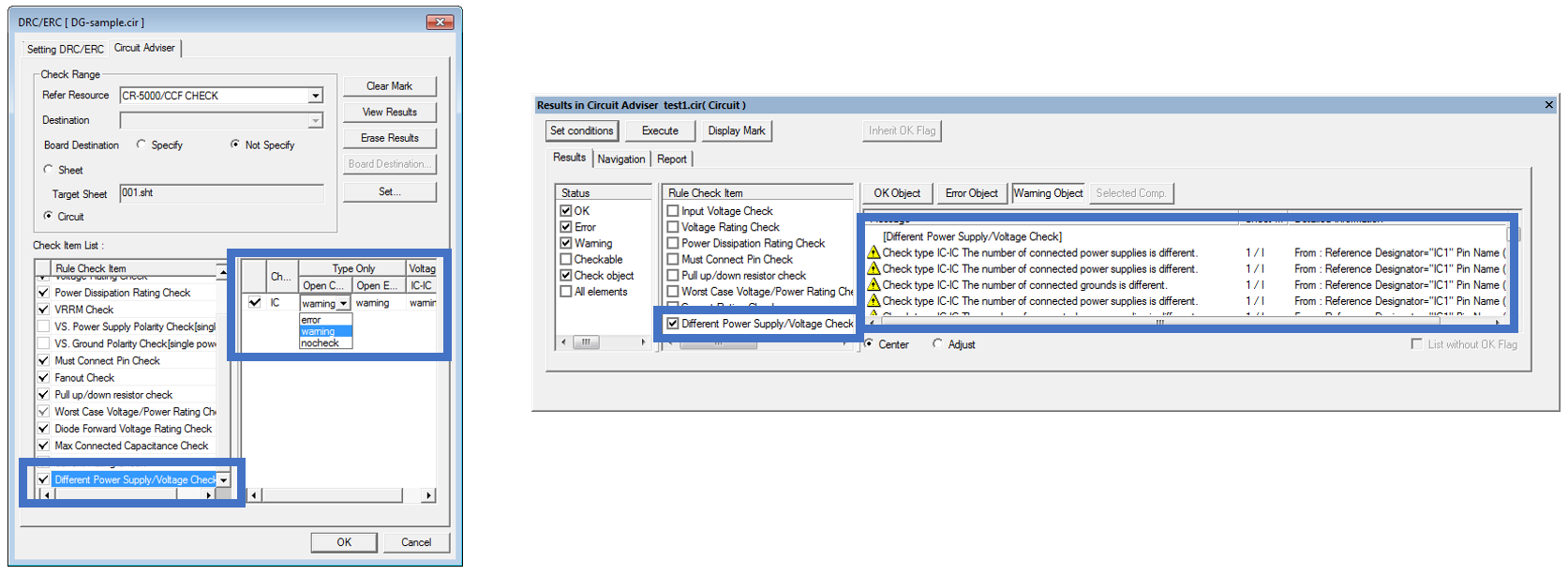
- The Design Rule Check can identify Power Supply and Ground net symbols (components), which exist only once in a design (single occurrence).
- Circuit Adviser can check whether power supplies are mixed.
- Design Rule Check In Variant Design: OK flags and comments in DRC and Circuit Adviser results can be inherited to other variants.
Inter-Board Connection Verification
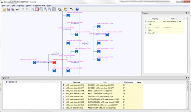
- Connections between different single circuits board can be traced in a simple view. The selection status can be probed to an object on Design Editor.
- The connection between physical connectors can be verified. The net label can be imported from a CSV file. Unmatching E-net labels can be identified.
- Connectors on system level can be displayed in a different style, depending on how they are connected on a board circuit level to identify redundant or insufficient connections on system level
Design Force
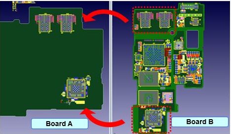
Templates and Technology Re-use
- Components can be placed as a template on a different board using a schematic block. Even when the number of layers differs between the source and destination boards, you can specify layer mapping to copy components.
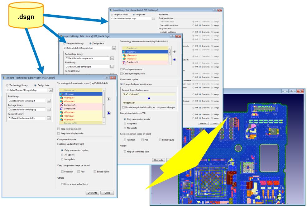
- Technology and design rules can be imported from another design into your current design.
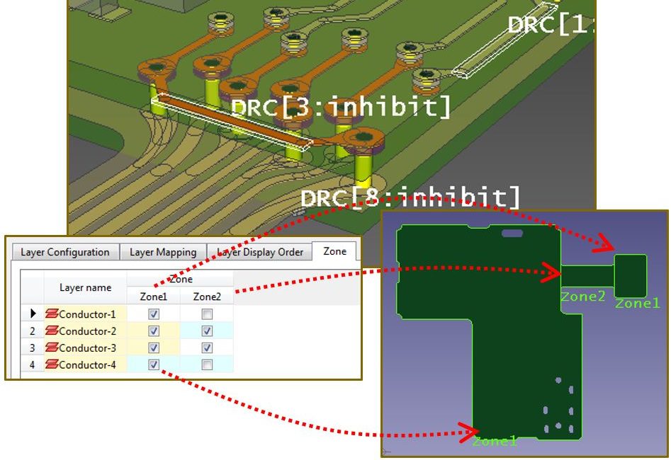
- Layout zones have been added as a new Board System Layer parameter. This allows you to create specific layer stacks for rigid-flexible boards.
Differential pairs and shield vias
- The Route to end option is now available when a differential pair is routed
- When a differential pair is moved, the track spacing will be adjusted according to the relevant rules. The number of editing steps required after routing work has been reduced
- Fillets can be applied to bundled tracks, respecting their current clearance.
- Shield vias can be generated automatically based on user-definable specifications
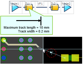
Virtual Branch Points and Nodes
- Virtual Branch Points can be specified, to split up a net into two branches at a certain point.
- With Virtual Notes it is possible to give length constraints to selected traces
- A mark will automatically be displayed at the location of the maximum track length, eliminating the need to check the track length.
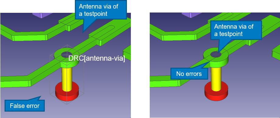
Design Rule Checks
- Testpoints can be excluded from Antenna Design Rule Checks
- Design Rule Checks support minimum pad widths, including restring
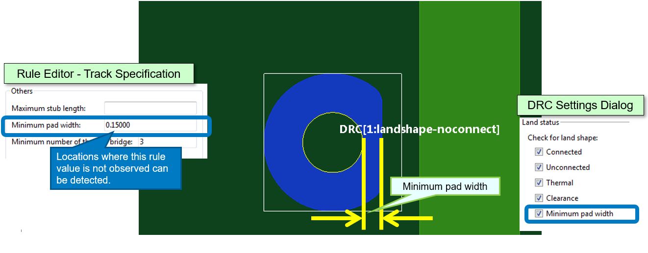
.
Subtract Area Fill an Offset Figures
- Overlapping area fills, which have a short circuit, can be corrected by subtracting either one, by Subtract Area Fill with Figure.
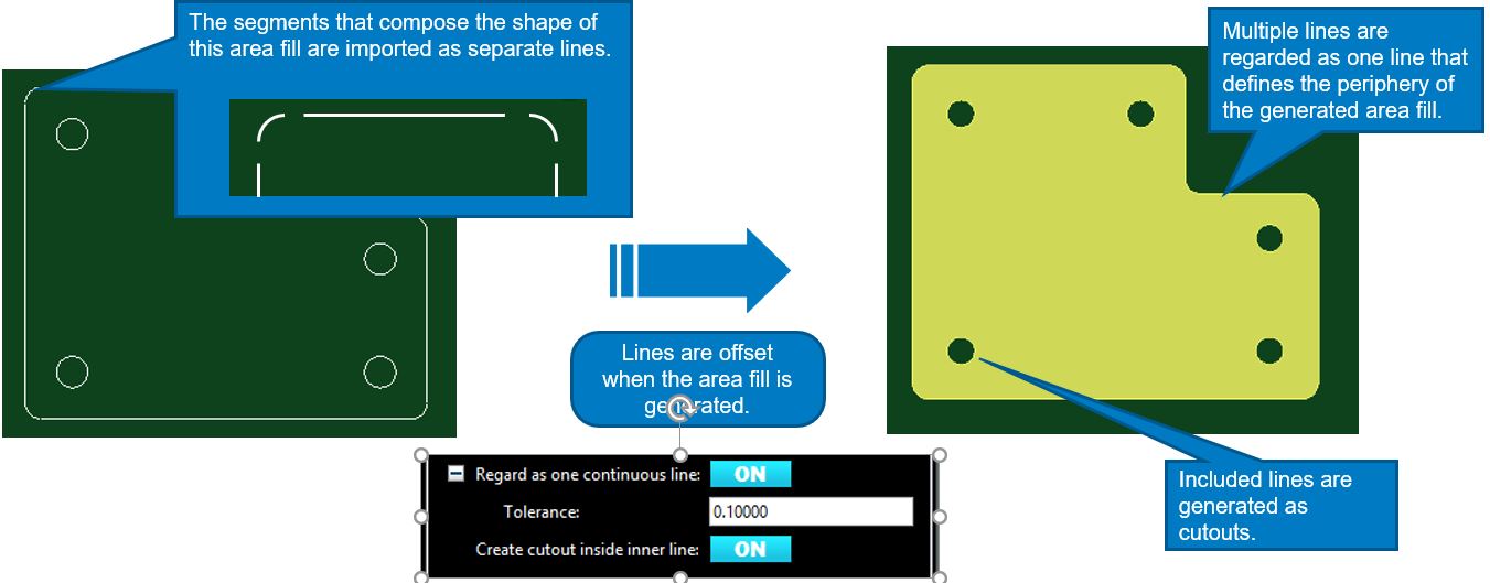
- Figures which are made of multiple single lines can be regarded as one single figure, to generate an offset figure. An offset can also generate cutouts if there is a shape inside of your reference figure.
.
Design Compare and Measurement
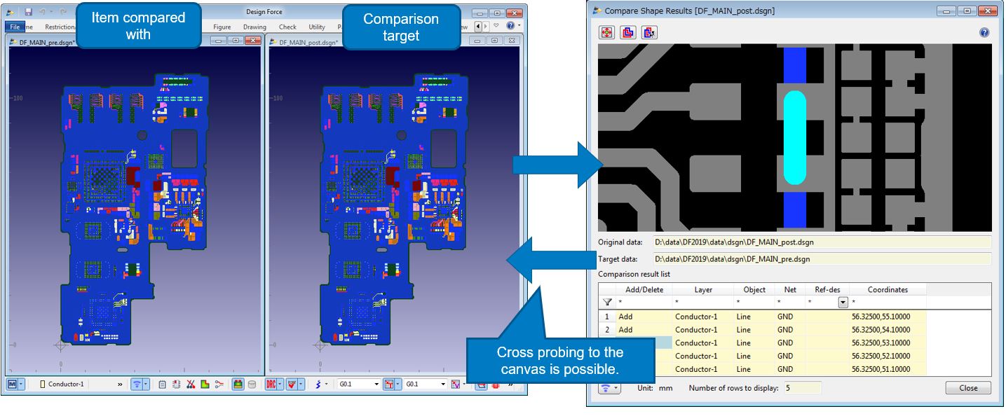
- Two open design files can be compared directly. The results can be highlighted on the canvas.
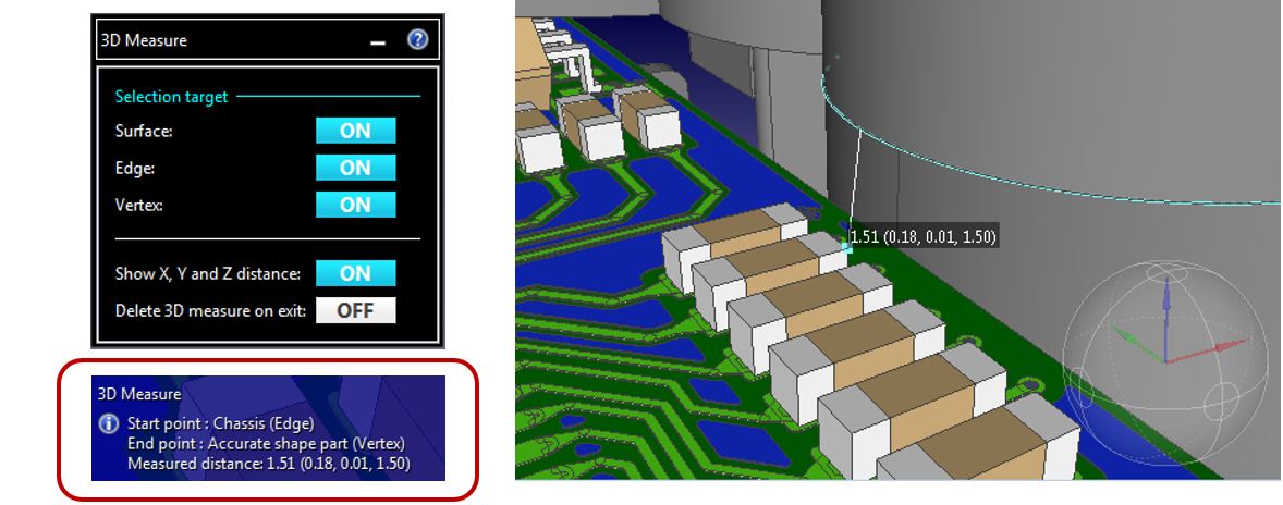
- The direct distance between geometries (surfaces, edges, and vertices) can be measured. Measurement results are displayed in a command balloon.
.