E3.formboard Basics: From Schematic to Build-Ready Harness Layouts
This article is part of our series Mastering E3.series with Harry. In Chapters 1 – 4, we focused on getting projects started, placing parts, making connections, and preparing outputs. Chapter 5 shifts from what connects to what (schematics) to how it’s built on the bench: E3.formboard. If you need technicians to build the same harness the same way every time, a clear formboard (nailboard) layout – complete with lengths, splices, tables, and protection – makes that possible.
Watch: Introduction to Formboard in E3.series (Video)
What is a formboard—and why does it matter?
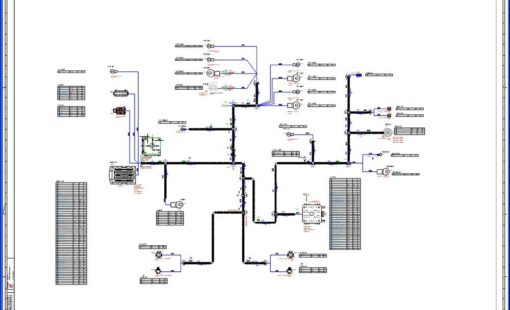
A formboard (or nailboard) is a full-size or scaled layout used to build and verify a harness. In E3.formboard, you translate logical intent into manufacturing geometry: branch routes, true cut lengths, splice locations, connector orientation, and the tables a technician relies on at the bench. The result is less ambiguity, fewer reworks, and faster builds.
When should I move from schematic to formboard?
Move once the logical design is stable enough to commit to physical routing. Typical signals you’re ready:
- Devices and connectors are selected and approved.
- Wire gauges, colors, and key signals are confirmed.
- Splices/taps and any EMC constraints (twists, shields) are known.
- Stakeholders have signed off on connectivity.
This timing helps you commit accurate manufacturing lengths without constant redraws.
How does E3.formboard differ from the schematic environment?
Schematics capture function; E3.formboard captures how to build. A few concepts set the stage:
- Formboard views of devices and connectors provide manufacturing-oriented symbols and tables.
- Manufacturing vs display length keeps the drawing tidy while preserving true cut lengths for production.
- Connector and splice tables sit near the hardware on the layout for quick reference.
- Core details “one row per core” make multi-core cables readable.
- Protection, twists, and shields are explicitly called out so assembly and compliance are correct the first time.
A practical path to your first formboard
Start by creating a Formboard sheet at an appropriate scale. Place the harness and Formboard connector views where the assembly will terminate. Route branches between them, then refine geometry with nodes and controlled angles. Use manufacturing length to lock accurate cut lengths and display length to keep the drawing readable.
Add splices where wires join and generate the splice table beside the layout. For multi-core cables, present core names, gauges, and colors – the “one row per core” option boosts clarity. Call out conduit or sleeving where protection is required, and mark twisted pairs and shield terminations for EMC-sensitive runs. Finish with connector tables and, if needed, extra front/top device views to eliminate guesswork during assembly and test.
What are common pitfalls—and how do I avoid them?
“My layout looks messy if I keep true lengths.”
Use display length to tidy the picture; never “fix” readability by changing manufacturing length.
“Technicians are unsure about connector orientation.”
Keep the connector table close to the view and add a front/top orientation view if ambiguity remains.
“Tables get out of sync after late changes.”
Re-run generated tables (don’t redraw) after edits so data stays synchronized.
“We can’t print 1:1 on a single page.”
Tile the output with clear overlaps/coordinates. The geometry and tables remain unambiguous for the bench.
What should I document for EMC-sensitive harnesses?
Call out twisted pairs (what to twist and how much) and show shield coverage and terminations (where the drain bonds or grounds). Consistent symbols and localized notes prevent assembly errors and speed inspection.
How do I make my formboards easier to read?
Consistency is your friend: naming, labeling, and table formats should match your schematic conventions. Keep tables local to the features they describe, use one row per core on dense cables, and group related notes. Small readability upgrades save minutes on every build—every day.
Next steps
If you’re new to formboards, convert one stable harness from your library and produce a pilot formboard. Ask the bench team two questions:
- What was ambiguous?
- Which tables helped most?
Fold their feedback into your template so every subsequent board benefits.
Have questions or feedback—or topics you want next? Email mastering-e3series@gb.zuken.com
Stay current with tutorials and best practices—subscribe to the Zuken blog: https://www.zuken.com/subscribe
Ready for deeper instruction? Explore Zuken training for E3.formboard, wire harness design, and control panel workflows at zuken.com.
Mastering E3.series — Chapters 1–4
- Chapter 1: Setting up your first E3.series project — project templates, sheets, workspaces
- Chapter 2: Adding components and connectors in E3.series — database parts, symbols, blocks
- Chapter 3: Connections, signals, wires & managing cables in E3.series — multi-connect, splices, twisted pairs/shields
- Chapter 4: Exports & reporting in E3.series — PDFs, BOMs, Report Generator workflows


- Blog
Build accurate dynamic cables in E3.series by defining cores, shields, and twisted pairs so schematics, reports, and formboard outputs stay consistent.

- Blog
E3.series automation is entering a new era as Microsoft phases out VBS. With the official Python package, Zuken offers a modern, future-proof way to automate E3.series while preserving all familiar capabilities.
- Blog
Use Fields in E3.series to stop splitting designs across multiple pages, keep device inheritance correct, and generate clean reports when multiple functions share one sheet.
- Blog
Use Fields in E3.series to stop splitting designs across multiple pages, keep device inheritance correct, and generate clean reports when multiple functions share one sheet.