System Design Hierarchy

System Design Software​

Menu

Streamline the Development Process​

E3.series integrates with various system design tools that help engineers design, analyze, and optimize complex systems. With analysis and optimization, engineers can study and examine data to gain insights and make informed decisions. As the demand for complex product systems grows, using system design tools has become increasingly important in engineering.

Streamline the Development Process​

Electrical Systems Topology Planning

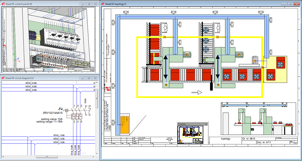
E3.topology takes logical designs into the physical world. Topology sheets created at any scale can be added to the overall E3.series project. Sheets can represent a vehicle’s chassis or a plant’s layout.

Subsystem installation spaces such as the dashboard or control panels are easily added to the topology sheets.

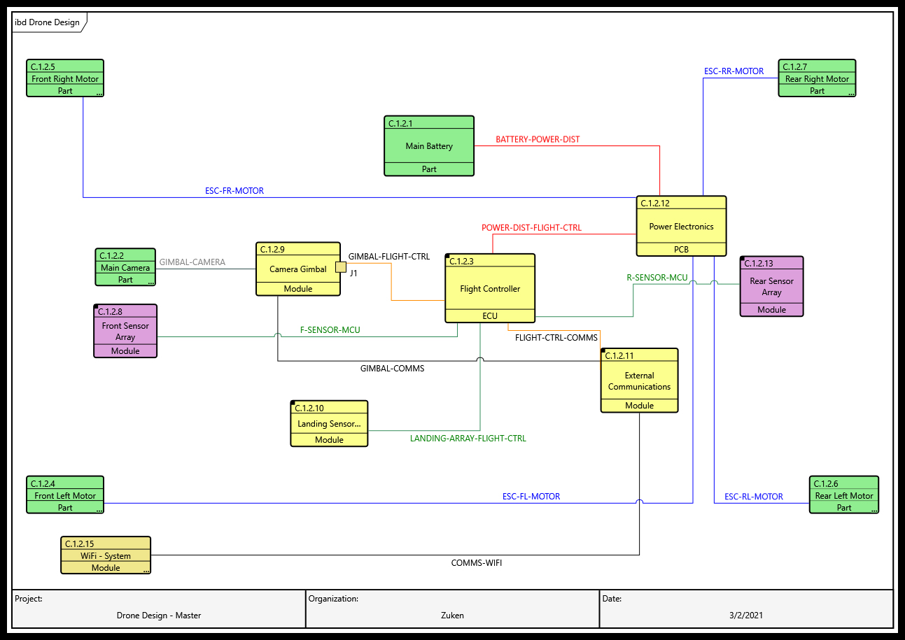
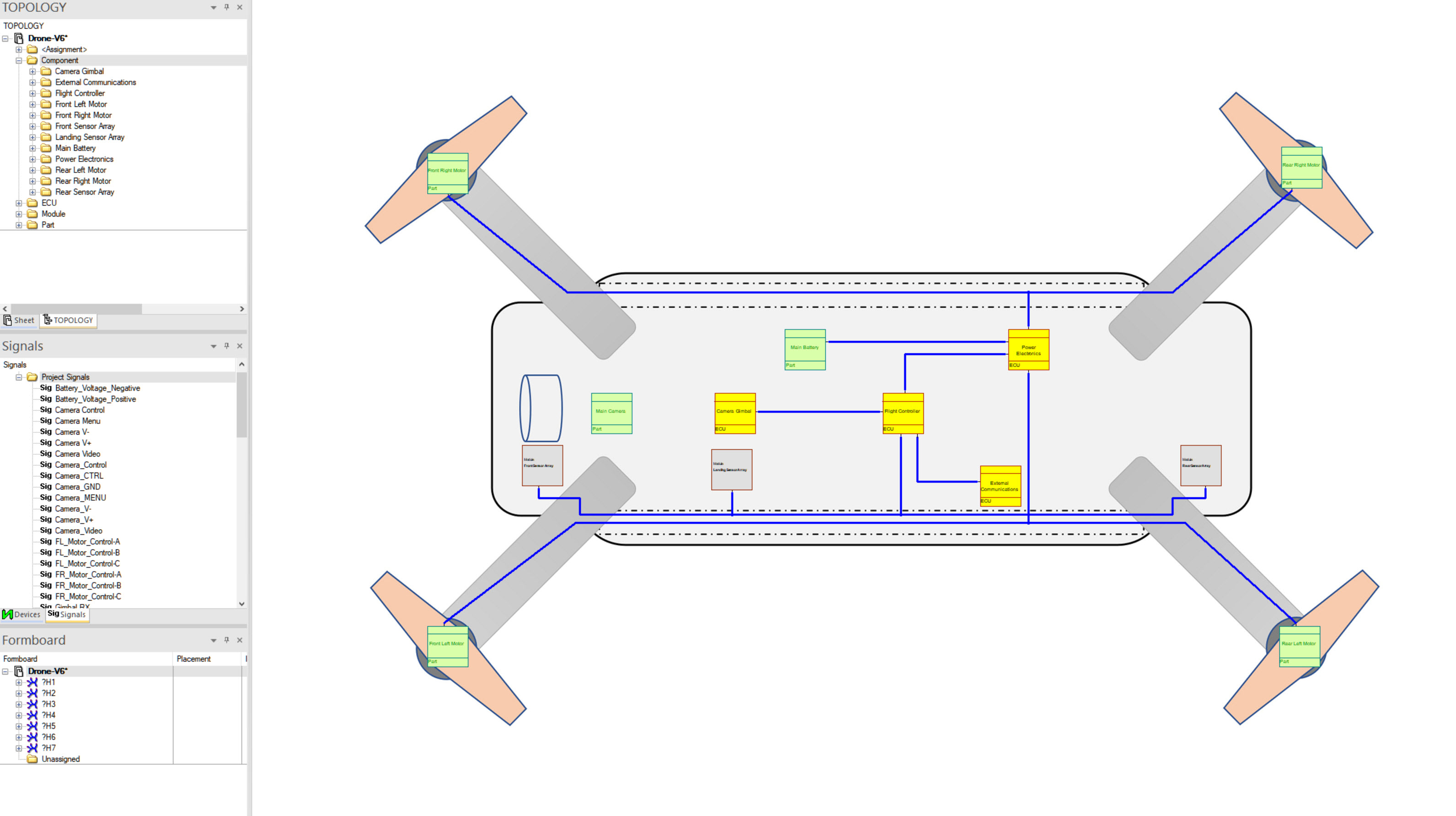
Define connection pathways between installation spaces and place components in the spaces. The connections between these installation spaces represent harness routes or cable trays. Alternate views of logical devices in the same project are placed into the relevant installation spaces.

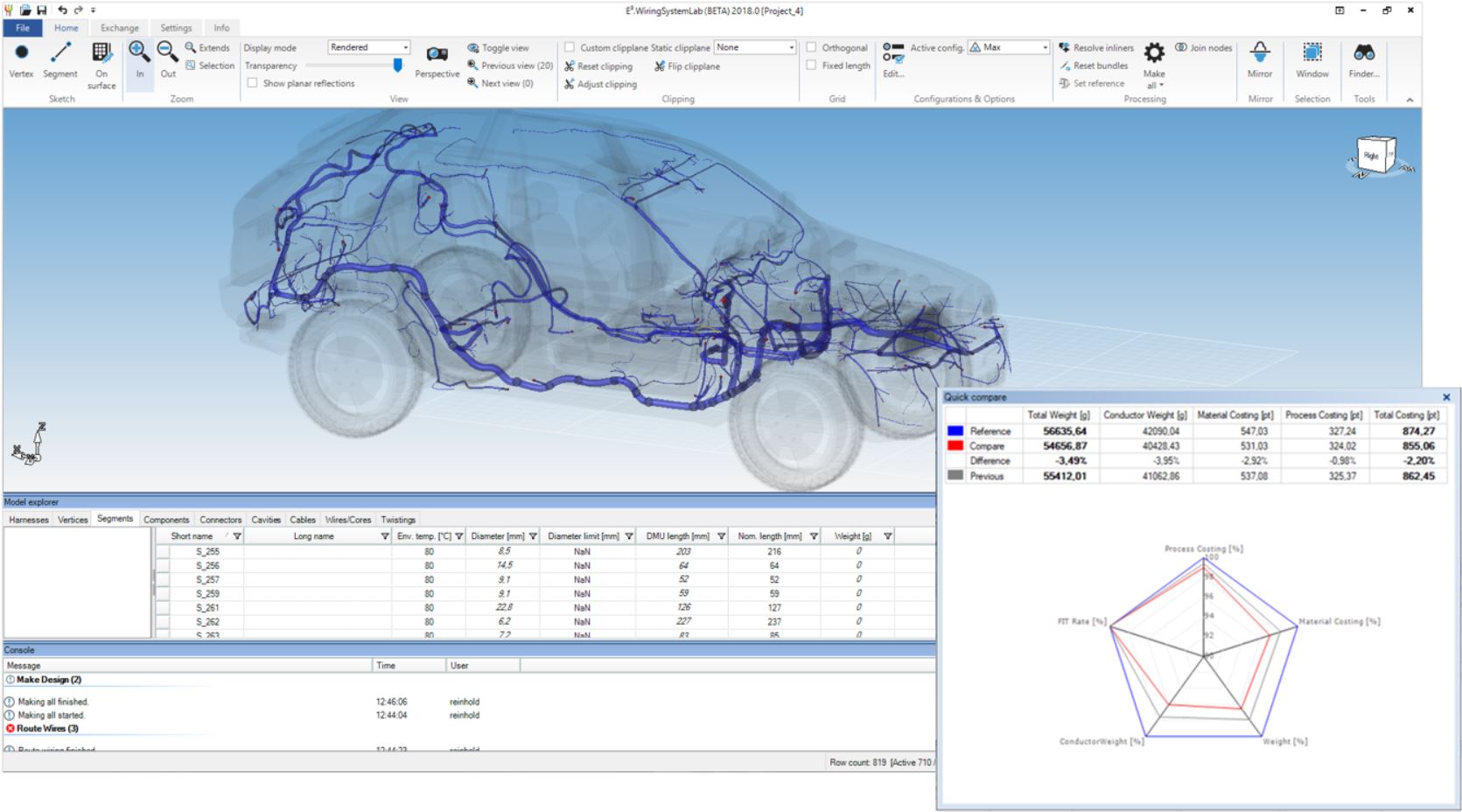
As the detailing process continues, the schematic’s signal logic and wiring information is automatically shown in the topology view. The harnesses or cable trays start to be automatically defined. Inline devices are easily added, and alternate configurations can be tested quickly. Special reports detail the routes, including cost and weight estimates.

E3.topology

E3 Vehicle Formboard

E3.wiringsystemlab

Wire Harness Analysis and Optimization

E3.WiringSystemLab enables the optimization of wire harnesses with unprecedented speed and accuracy. With these capabilities, it generates substantial benefits across a wide spectrum of applications in the automotive and transportation industry. Optimize using AI methodologies to determine weight and cost enabled by models developed by ZukenWith the ability of different variants and configurations within one single project enables the evaluation of different implementation approaches. E3.WiringSystemLab offers powerful analysis and compares functionality to help engineers determine the most suitable solution in a minimum amount of time. E3.WiringSystemLab supports standard formats such as KBL, VEC, PLM XML, or Excel® ensures easy integration into CATIA® or Siemens NX® environments.

Optimizing wire harness designs to meet targeted weight and cost objectives is complex and challenging. One of the most time-consuming aspects is consolidating different data sources and inputs into one consistent representation. Topology data, in particular, have been known to require an intense effort for consolidation, as different segments must be combined into one single representation and then routed manually in a 3D environment (e.g., CATIA® or Siemens NX®).

E3.WiringSystemLab simplifies this complex task with direct 3D data modeling capabilities and automated wire harness assembly functionality, supporting compiling comprehensive harness designs from heterogeneous fragments. The result is a substantial reduction of ramp-up and optimization cycles.

E3.WiringSystemLab is committed to supporting all relevant industry-standard formats, such as KBL, VEC, PLM XML, and generic Excel files. With its support of the VEC format, E³.WiringSystemLab leads the industry by anticipating the next-generation industry standard for wire harness designs. For the customer, this means substantial benefits in terms of easy integration into existing environments and the protection of investments in legacy data. 

E3.WiringSystemLab integrates seamlessly into existing E³.series environments, reading in schematics data directly from the E³.cable data model. A process-to-process coupling provides information between the toolsets. No file transfer is required to read schematic information into E3.WiringSystemLab. A highlighting functionality enables cross-probing between E3.WiringSystemLab and E3.cable. This cross-reference is maintained through the technology repartitioning process and becomes available in E3.HarnessAnalyzer in combination with the related 3D structure.

Topology structures can be accessed and manipulated directly in a 3D environment. Particular attention was dedicated to an intuitive user interface enabling casual users to access and modify 3D structures without requiring specific training. Powerful yet easy-to-use functionality is also available to support typical topology modification tasks, such as inserting connectors and packaging components by drag & drop or 3D mirroring.

To compare different implementation approaches, E3.WiringSystemLab provides powerful concept evaluation capabilities. An online indicator is available directly in the user interface, indicating trends for key values. Access details with just one additional click. In addition, a dedicated comparison tool is available that visualizes differences between versions on a detailed level down to single wires or connectors.

Transition Models to Detailed Design

Connect system architecture to establish detailed design using the E3.GenesysConnector. Any communication breakdowns within the organization can result in product development defects. The E3.GenesysConnector system design can seamlessly transition or expose the model to the detailed design team helping to prevent communication breakdowns. 

The plug-in intelligently transitions the data through a process that adds the relevant details from the system model. These design envelopes can consist of diagrams, requirements, parameters, and verification requirements. The design team then knows the acceptable parameters in terms of cost, weight, size, power, etc, are

Digital Engineering - Drone Design asFlowIBD

Figure-4-E3.series-Topology-with-Drone-ibd

  • Connect with PCB tools using standard manufacturing outputs 
  • Establish architecture context for detailed designs
  • Push signals and links to reuse established connections
  • Track parameters and requirements
  • Communicate updates

IPC-2581 is a printed circuit board assembly manufacturing description data and transfer methodology standard. IPC-2581 enables the transfer of comprehensive PCB design. The IPC-2581 Importer consumes the IPC-2581 file and transitions the I/O connection information from printed circuit board designs to the detailed design. With this detail, quickly define the harness connectors and signals. Eliminate the risk of errors and improve the efficiency of data conversions.

Got a Question? - Contact Zuken today

For more information on how Zuken can help your design process, contact Zuken today.
Contact us today