
What Is a PLC Control System? A Guide to the Basics
A programmable logic controller (PLC) is an industrial computer that monitors inputs, executes programmed logic, and controls outputs. PLCs coordinate physical equipment in manufacturing facilities, utility systems, and building automation. This guide explains PLC control system basics, including how PLCs work, how they connect to field devices, how they are programmed, and how they support reliable electrical design.
Quick answer: A PLC continuously reads field inputs, executes control logic, and updates outputs to automate equipment. Its I/O modules connect the controller to sensors and actuators, while an HMI or SCADA system provides operators with a way to monitor and control the process.
What Is a Programmable Logic Controller (PLC)?
A PLC is a computer designed for industrial automation control. Unlike a standard consumer-grade computer, a PLC is built to operate continuously in harsh environments where equipment may be subjected to vibration, heat, dust, and moisture. There is no traditional operating system (OS). Instead, control engineers use an Integrated Development Environment (IDE) that Control Engineers use to program the PLC. The OS is designed to run unattended 24 hours a day, 7 days a week.
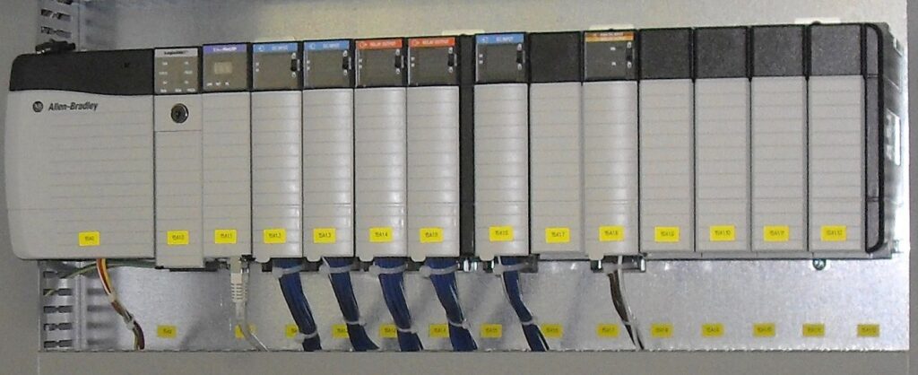
https://en.wikipedia.org/wiki/Allen-Bradley#/media/File:BMA_Automation_Allen_Bradley_PLC_3.JPG
Once deployed, PLCs drive machinery, equipment, and automated processes. They read inputs from field devices such as sensors and meters, follow programmed logic, then send outputs that tell devices like valves, motors, pumps, and switches what to do. PLCs act as the brains of the operation in many manufacturing, utility, and infrastructure applications.
How Does a PLC Control System Work?
At its core, a PLC system consists of inputs, logic, and outputs. Inputs tell the PLC what is happening in the field. The PLC logic evaluates that information, and outputs send control signals to devices such as pumps, valves, motors, lights, or alarms.
A simple water tank example makes it easier to understand what a PLC is in practical terms:
- Inputs: Sensors tell the PLC whether the water level is too low, within range, or too high.
- Logic: The PLC program decides what should happen based on the sensor signals.
- Outputs: The PLC sends commands to the pump and valve to adjust the water level.
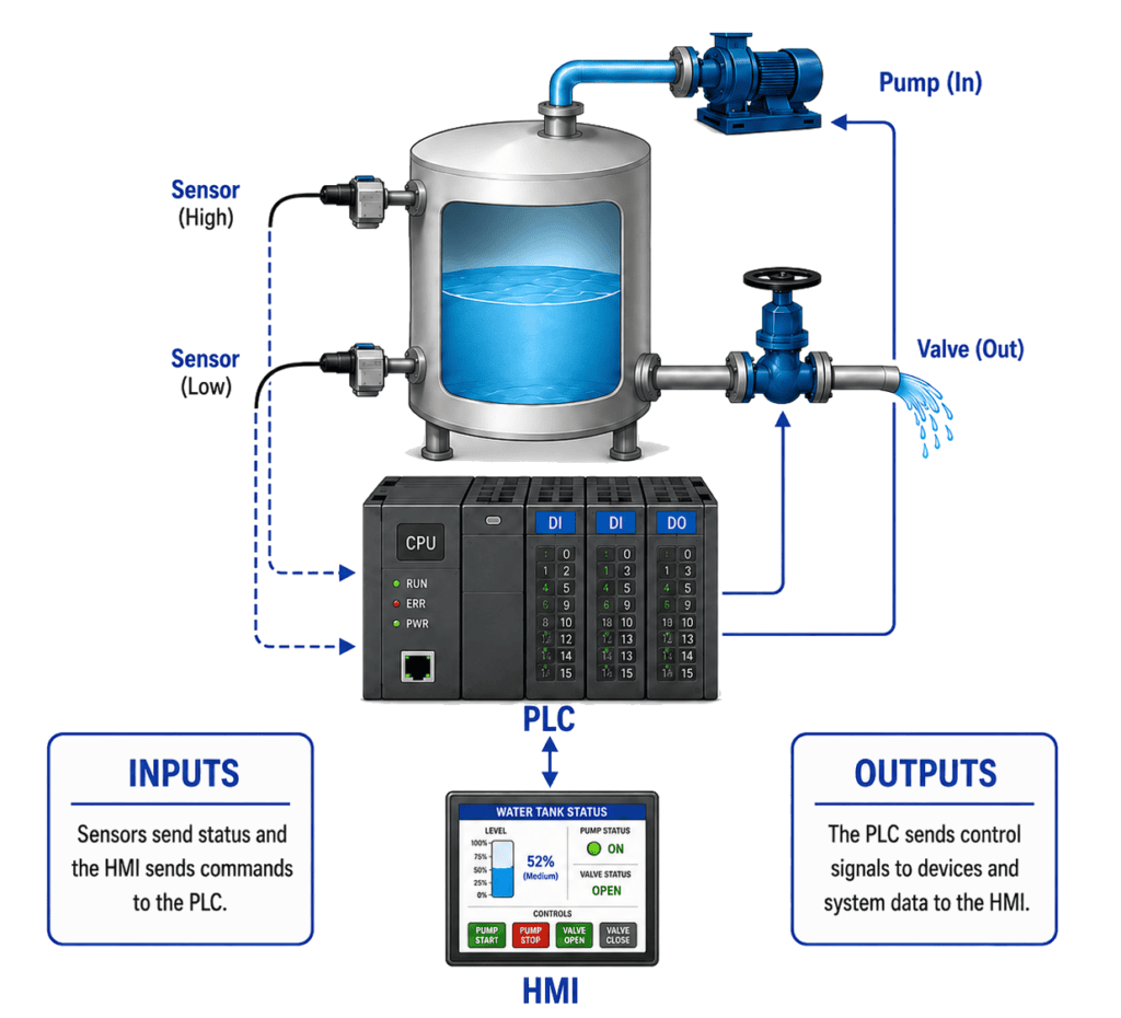
If the low-level sensor detects that the tank is running low on water, the PLC activates a pump to refill it. The pump continues running until the water reaches the high-level sensor. The valve could also be manually controlled via a Human Machine Interface (HMI), allowing the operator to open it when necessary. The PLC serves as the decision-making controller, instructing field devices on what to do.
This input-process-output cycle applies across many industrial systems, from conveyor lines and packaging machines to wastewater plants and building automation systems.
How PLCs Connect to Equipment
A PLC can only control equipment when it receives information from the field and sends commands back to connected devices. I/O (input/output) modules, field wiring, and industrial communication networks create this connection.
I/O modules serve as the interface between a PLC and the field devices it monitors and controls. They convert and condition signals from sensors, switches, transmitters, motors, and other equipment into formats the PLC can process. They also convert PLC commands into signals that field devices can use. Because industrial devices often use standardized signal types—such as discrete 24 VDC, 4–20 mA, 0–10 VDC, and industrial communication protocols—engineers can connect them to PLCs from different manufacturers.
Engineers select I/O modules based on the PLC platform, field device types, signal requirements, communication protocols, environmental conditions, and the number of input and output points the application requires.
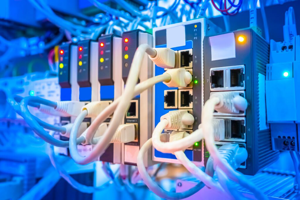
Connections can be made, depending on the application, via traditional wiring, Ethernet, fiber, or a mix of methods. A flow meter, for example, may send an analog signal over a twisted-pair wire to an I/O module. Meanwhile, larger PLC systems may use Ethernet or fiber to connect remote I/O cabinets, operator stations, and other control hardware. The devices also need to use the same industrial protocol, such as Ethernet/IP, Modbus, PROFIBUS, or PROFINET, so the PLC and connected equipment can exchange information correctly. Using proprietary communication protocols in a single PLC rack is possible, but should be avoided if possible.
Together, field wiring, I/O modules, and industrial communication networks create the link between programmed control logic and the physical equipment in the field.
How are PLCs Programmed?
A PLC needs programmed logic to know how to respond to different inputs, operating conditions, and equipment states. There are several common programming methods:
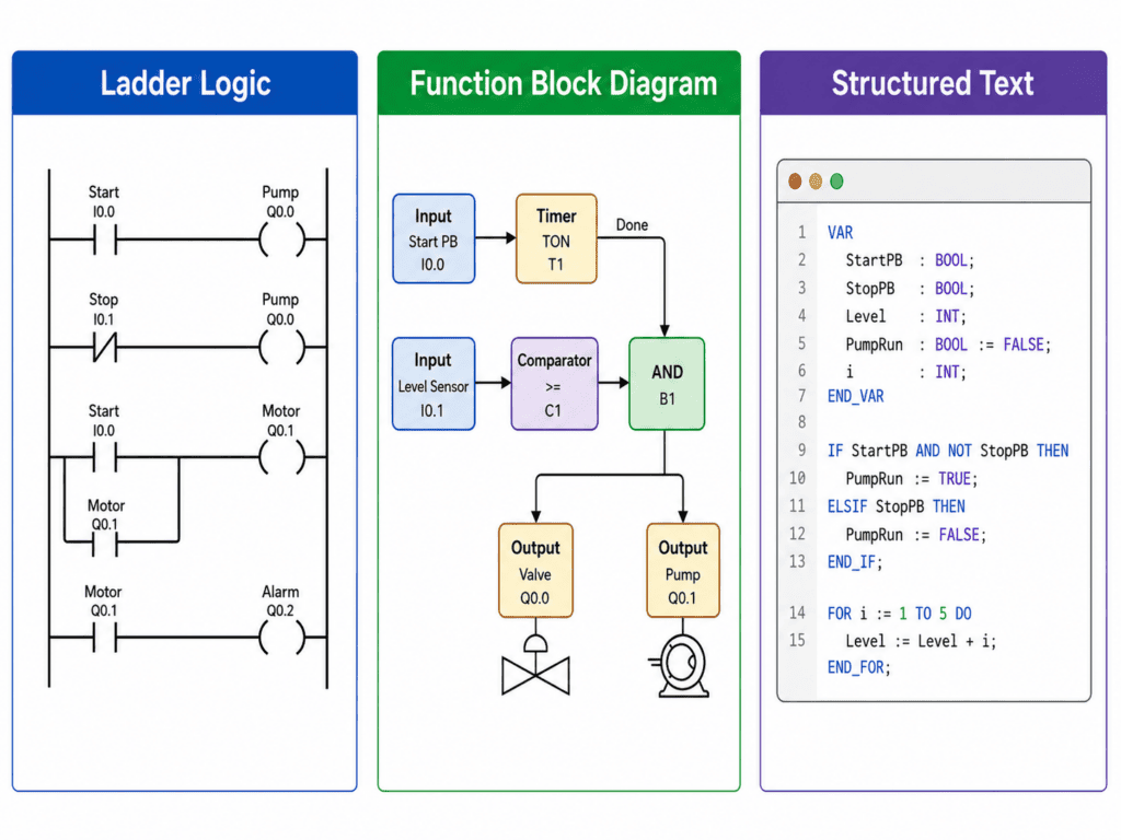
- Ladder logic: This traditional format looks like an electrical schematic and is often the easiest for field technicians to interpret, especially for simple systems.
- Function block diagrams: These diagrams represent logical functions as connected blocks, balancing detail and readability.
- Structured text: Structured text looks more like traditional software code and is ideal for complex logic and dynamic applications.
PLC systems can be programmed using any combination of methods, provided the PLC supports those formats. Depending on the application, the PLC could be using Ladder Logic for motor control, Function Blocks for temperature control, and Structured Text for complex calculations. The best programming method depends on the system’s complexity, maintenance requirements, and who will support the system over time. As programs grow to include more I/O points, control sequences, and operating conditions, it becomes increasingly important to maintain clear naming and organization within the PLC program.
How do Operators Interact with the PLC
In practice, most operators do not interact directly with the PLC. Instead, they use an HMI (Human-Machine Interface) or a SCADA (Supervisory Control and Data Acquisition) system to communicate with it.
An HMI is typically a touchscreen display mounted on a machine or control panel. It allows operators to view equipment status, start and stop processes, adjust settings, and acknowledge alarms. The HMI sends operator commands to the PLC, and the PLC executes the required control actions.
A SCADA system provides similar functionality but is usually installed on one or more computers and can monitor and control multiple PLCs throughout a facility. In addition to displaying real-time operating information, SCADA systems often provide alarm management, data logging, historical trends, and plant-wide monitoring capabilities.
For example, an operator might use an HMI or SCADA screen to start a conveyor, view a tank level, or change a motor speed. The PLC receives these commands and controls the equipment accordingly. In this way, the PLC performs the control functions while the HMI and SCADA systems provide a user-friendly interface for operators
How E3.series Supports PLC Control System Design and Documentation
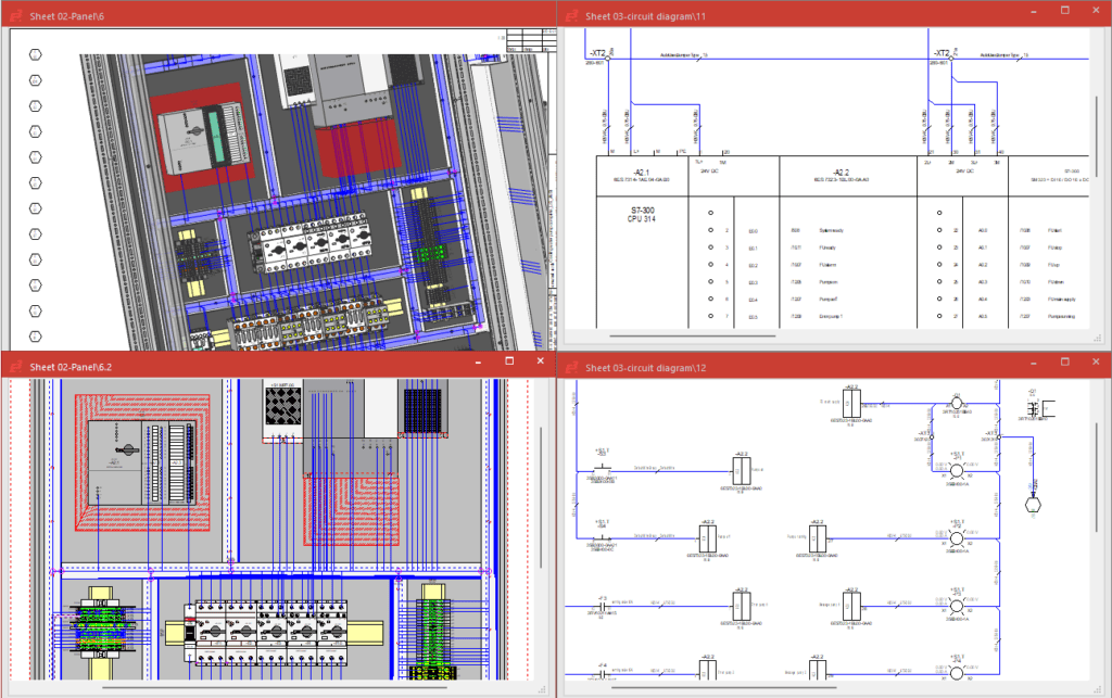
Designing a PLC control system requires accurate electrical documentation. With E3.series, engineers can create schematics for PLC racks, I/O cards, field devices, and wiring. Next, engineers can build panel layouts with rules-based, 2.5D placement to ensure PLC components fit within electrical enclosures. All devices connected to the PLC are clearly documented both electrically and mechanically.
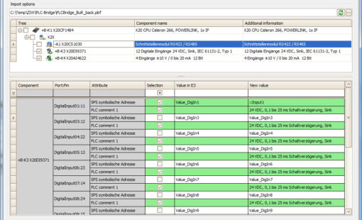
In addition, Zuken helps hardware and software teams collaborate during PLC programming. Its PLC address management tool automatically assigns addresses based on the predefined syntax for each PLC component. Those physical addresses, symbolic addresses, and descriptions can be exported to PLC programming tools, helping both electrical and software engineers keep documentation and control program aligned.
Ready to learn more? Explore how E3.series supports electrical control systems design:
- Watch: Reduce errors in control cabinet designs using E3.series
- Read: How visualization impacts panel design and manufacturing
- Explore: Product pages for panel and E3.PLCBridge

-
Applications Engineer



- Blog

- Blog

- Blog

- Blog
Related Products and Resources
- Blog
- Products
- Products

- Products
E3.series is a Windows-based, scalable, easy-to-learn system for the design of wiring and control systems, hydraulics and pneumatics. The out-of-the-box solution includes schematic (for circuit and fluid diagrams), cable (for advanced electrical and fluid design), panel (for cabinet and panel layout), and formboard (for 1:1 wiring harness manufacturing drawings). Integrated with MCAD, E3.series is a complete design engineering solution from concept through physical realization and manufacturing output.