Tech-Tip: Design Synchronization Tool
When your design is nearing completion and you want to make sure the schematic matches what you have in your board try using the Design Gateway, Design Synchronization Tool. You can use this tool to check your schematic data against your board data. Detect differences in variation, netlist, and component attributes by comparing circuit data and board data.
To make a comparison between circuit data and board data follow these steps:
- From the [Circuit data type] drop-down list, select the type of the following circuit data.
- Design Gateway (SDM)
- Design Gateway (CIR)
- Intermediate file (NDFC)
- From the [Circuit data type] drop-down list, select the type of the following circuit data.
- Design Gateway (SDM)
- Design Gateway (CIR)
- Intermediate file (NDFC)
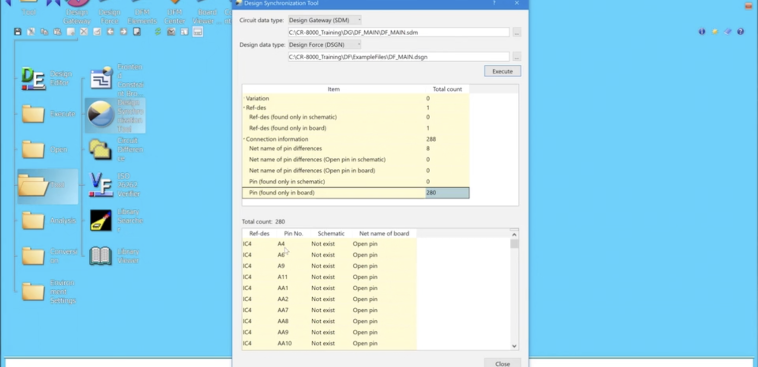
- Click the [Execute] button. This makes a comparison between circuit data and board data.
Check the result of the comparison between circuit data and board data.
- From the list, select the item you want to check.
Comparison items
- Variation destination type differences
- Part name of ref-des differences (Considering variation)
- User attribute of ref-des differences (Considering variation)
- Ref-des (found only in schematic)
- Ref-des (found only in board)
- Net name of pin differences
- Net name of pin differences (Open pin in schematic)
- Net name of pin differences (Open pin in board)
- Pin (found only in schematic)
- Pin (found only in board)
Check out our other Tech Tips here!

-
Applications Engineer

- Blog

- Blog
- Blog

- Blog
Related Products and Resources
- Products
PCB Design Creation - Design Gateway is a platform for logical circuit design and verification of single and multi-board system-level electronic designs. It supports a true system-level circuit design in which individual circuits can be represented and connected as blocks.

- Products
Building a competitive product today is much more difficult than a few years ago. Existing PCB-centric design processes are limited to a single PCB and do not provide the necessary tools for today’s competitive product development environment. PCB-centric design processes are falling behind.