Bridging the Gap Between MCAD and ECAD: Why E3.3DPanelBridge Matters
Menu
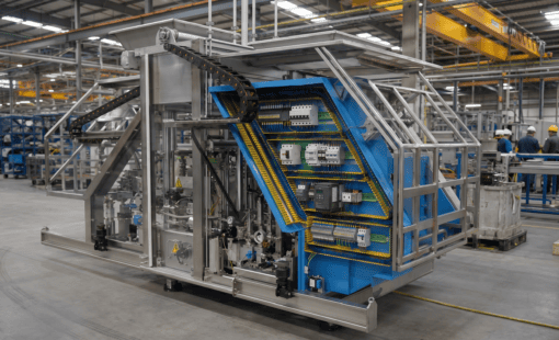
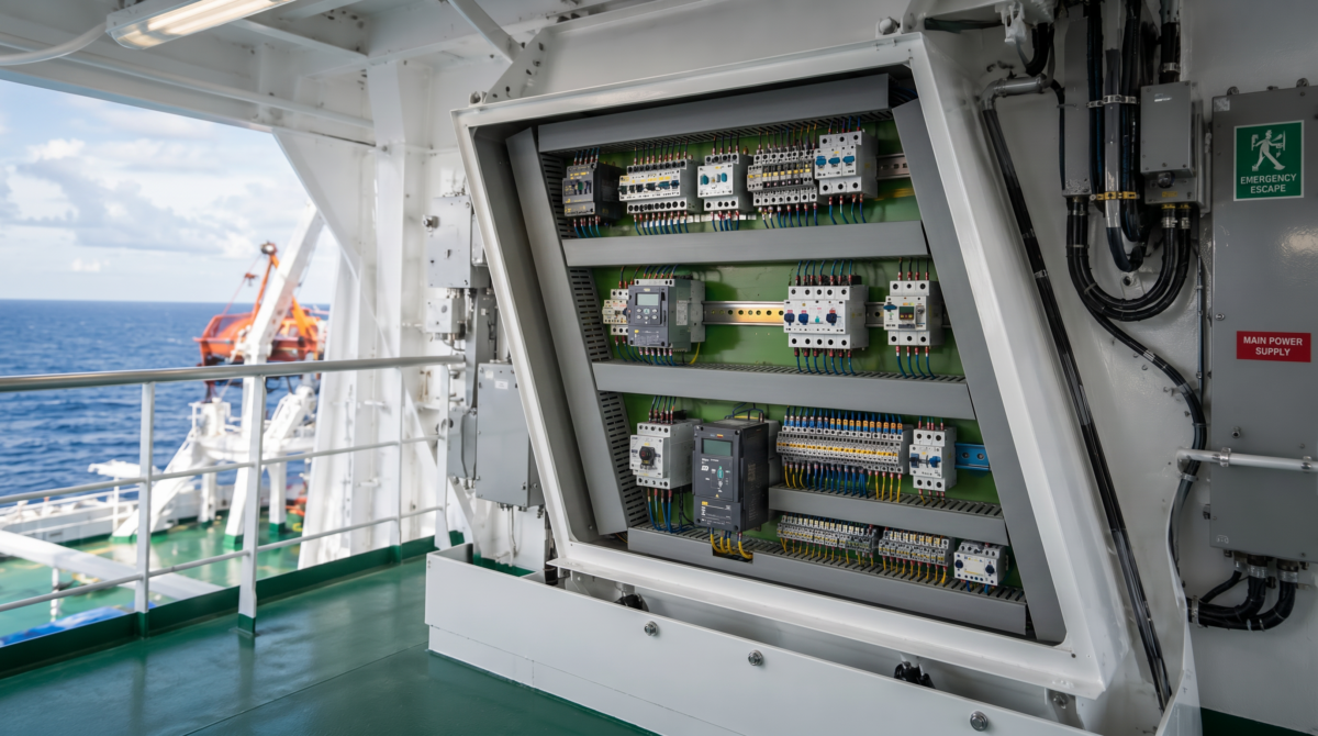
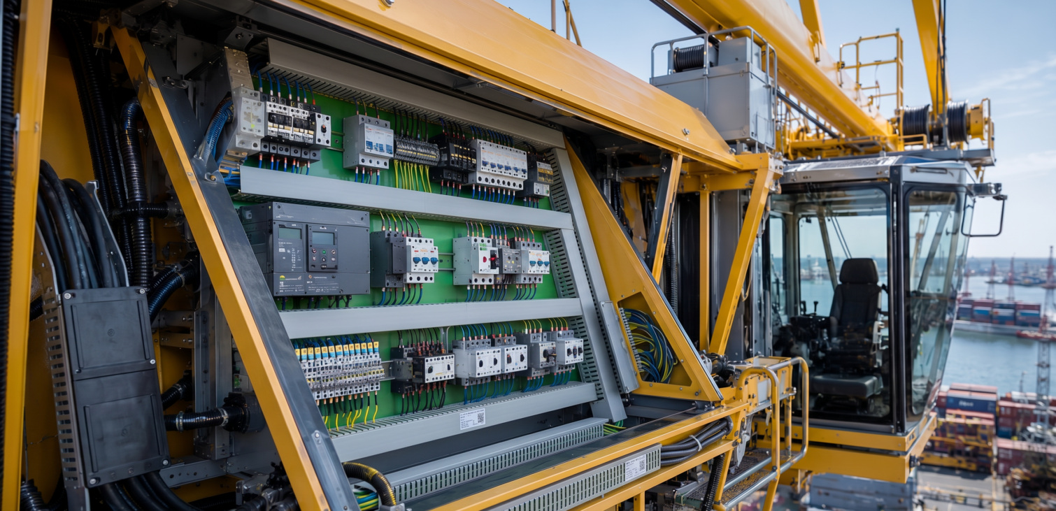
In modern machines, vehicles, and industrial equipment, space is no longer a luxury. Electrical components are often no longer installed in large, dedicated control cabinets. Instead, they have to fit into tight mechanical spaces — inside machine frames, vehicle modules, compact enclosures, or complex installation areas.
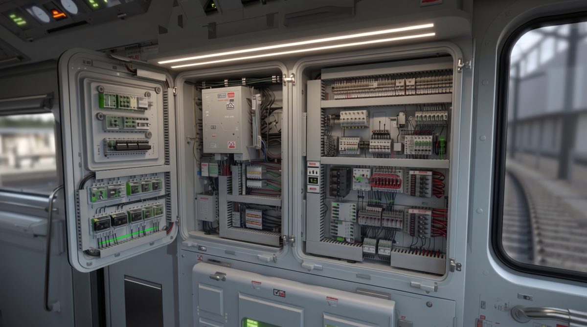
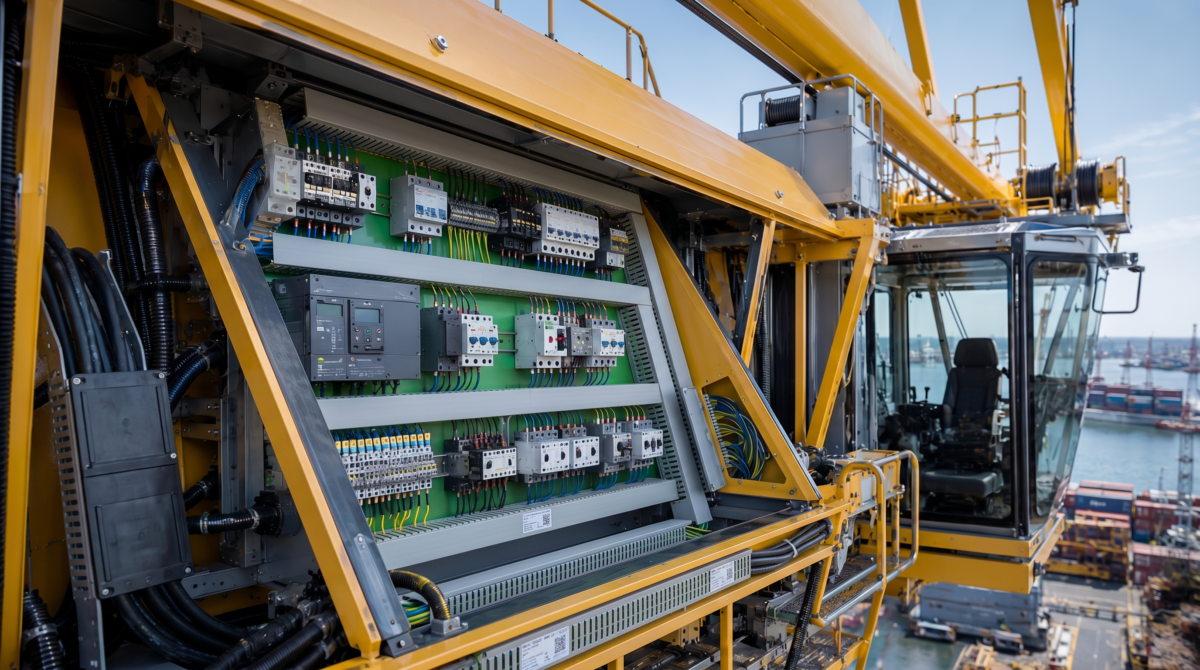
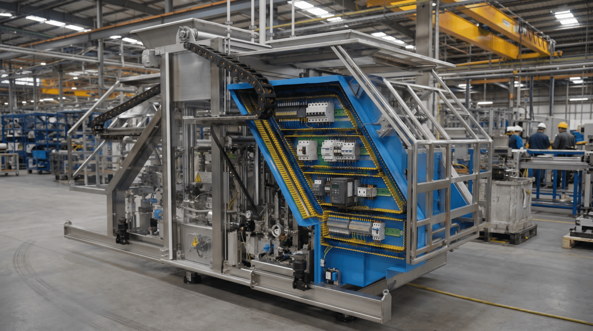
That creates a real challenge for engineering teams.
Mechanical design and electrical design can no longer happen in separate worlds. The mechanical team defines the available space. The electrical team needs to place devices, route wires, calculate lengths, and validate the layout. If both sides are working with disconnected data, problems usually appear too late — during assembly, review, or even production.
This is exactly where E3.3DPanelBridge comes in.
From Mechanical Space to Electrical Intelligence
E3.3DPanelBridge connects mechanically defined installation spaces with the electrical design workflow in E3.Panel.
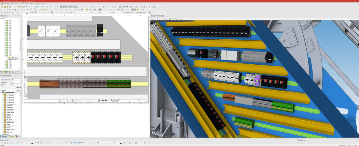
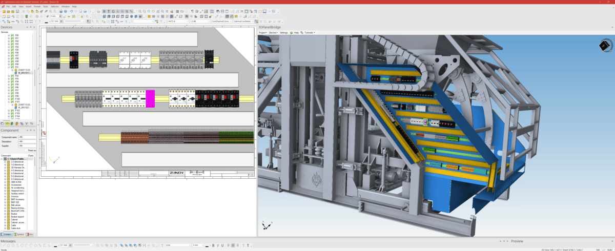
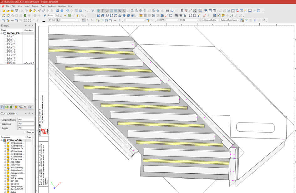
The process starts with a STEP-based mechanical layout. This layout can include mounting plates, mounting rails, and cable ducts. These structures are imported through E3.3DPanelBridge and transferred into E3.Panel, where they become the foundation for the electrical layout.
The key point: electrical device placement still happens in the familiar E3.Panel environment. Users continue to work with the standard E3.Panel functionality they already know — but now within a layout that reflects the real mechanical installation space.
Devices such as contactors, terminals, circuit breakers, and other electrical components can be placed on the imported mounting rails. Based on that placement, E3.Panel can generate important engineering results such as wire lengths, routing information, and cable duct fill levels.
3D Visualization Where It Matters
Once the electrical devices have been placed in E3.Panel, E3.3DPanelBridge can visualize them in the context of the original 3D mechanical environment.
This gives engineering teams a much clearer understanding of the actual installation situation. Instead of validating an electrical layout in isolation, users can see how the placed components relate to the real mechanical structure.
That helps with practical checks such as space validation, collision review, and early design verification.
The goal is not to replace E3.Panel as the main design environment. The goal is to add a strong 3D validation layer around the electrical layout — exactly where mechanical and electrical design need to meet.
Built for Real Engineering Changes
In real projects, mechanical designs change. Mounting plates are resized. Cable ducts move. Rails are added, removed, or repositioned.
This makes update capability critical.
E3.3DPanelBridge supports this through a controlled update workflow. Since STEP data typically contains geometry but not stable object IDs, updates cannot simply rely on fixed identifiers. Instead, the application compares the old and new geometry and tries to recognize existing objects based on position, orientation, size, and shape.
Where the system can identify a match, it creates an automatic mapping. Where the geometry has changed too much, the user can manually map old and new objects.
This two-step approach helps preserve existing E3.Panel data while still allowing the mechanical design to evolve.
More Than a One-Time Import
E3.3DPanelBridge is not just about importing a STEP file once.
It supports a workflow where panel extract data can be embedded into the E3 project. This means the relevant data can be saved together with the E3 design and reloaded later from the corresponding 3D panel sheet.
For special cases, panel extracts can also be exported as separate PEX files. This makes it possible to reuse a mechanical panel layout in another E3 project, for example when different electrical designs share the same mechanical installation structure.
A Practical Bridge Between Two Worlds
E3.3DPanelBridge brings together two engineering domains that often need to work more closely than traditional workflows allow.
It helps mechanical and electrical teams work from a shared installation context. It supports realistic electrical placement in E3.Panel. It enables 3D validation of the placed devices. And it provides update mechanisms for iterative MCAD changes.
In short, E3.3DPanelBridge connects mechanical space with electrical intelligence.
For companies working with compact machines, vehicles, modular equipment, or complex installation spaces, this can make the engineering process more transparent, more reliable, and better prepared for real-world manufacturing.

Dipl.-Ing. (FH) Reinhold Blank, born 1960, studied mechatronics at the Technische Hochschule Nuremberg. Since 1990 he is working in the domain of E-CAD, first in sales, then as support manager and head of product management at well-known German software houses. In 1997 he changed the allegiance and took the worldwide responsibility as CAD-Manage for LEONI – one of the leading harness suppliers. Later he changed to Intedis – a JV company of the LEONI and HELLA and as member of the executive management he supported more than 100 projects for OEM´s worldwide in the area of E/E Architecture development. Along with those project he had established also a software development team at Intedis developing the first tool for E/E Architecture in 2003. In the recent years he gained also international experience while he was serving as General Manager of Intedis Shanghai.
Since May 2014 Reinhold Blank took the responsibility Business Director Automotive at ZUKEN´s E3 GmbH in Germany and is responsible for Zuken's solutions of today and tomorrow for the E/E systems in vehicles.

- Blog
July 13, 2026
From Formula 1 to Rapid Prototyping: How Alpine Tech Accelerates Innovation with E3.series
Discover how Alpine Tech is applying Formula 1 engineering expertise to help customers accelerate product development with rapid prototyping and E3.series.
Read now

- Blog
March 10, 2026
E3.series Dynamic Cables: Cores, Shields, Twisted Pairs
Build accurate dynamic cables in E3.series by defining cores, shields, and twisted pairs so schematics, reports, and formboard outputs stay consistent.
Read now
Mastering E3.series #8

- Blog
February 10, 2026
Future-Proofing E3.series Automation in a Post-VBS World
E3.series automation is entering a new era as Microsoft phases out VBS. With the official Python package, Zuken offers a modern, future-proof way to automate E3.series while preserving all familiar capabilities.
Read now
- Blog
January 26, 2026
E3.series Levels: Control Visibility and Hide Part Numbers
Use Fields in E3.series to stop splitting designs across multiple pages, keep device inheritance correct, and generate clean reports when multiple functions share one sheet.
Read now
Mastering E3.series #7