Eliminate documents. The model is connected to the design process eliminating the need for document generation.


Model-Based Engineering (MBE) is the implementation phase of product development. The model contents are segmented into electrical and electronic subsystem implementation assignments. Each assignment includes a design envelope guiding the detailed design team’s implementation. The design envelope provides multi-domain requirements.

Eliminate documents. The model is connected to the design process eliminating the need for document generation.

Design envelope. The model provides engineering with an implementation “design envelope,” providing freedom and guidance to the development team.

Eliminate errors. Verification events defined in the model assure the consistency between the design and implementation.

Traceability. The model history provides traceability eliminating the “how did we get here” experience.
Today’s biggest challenge for model-based design is transitioning to implementation or detailed design. Many companies convert their model back to documents, disconnecting the model from the design process. Ideally, a design envelope for each E/E subsystem is directly transferred and exposed to the design teams for implementation.


The model is segmented into work assignments for implementation. Imagine an aircraft with hundreds of E/E subsystems and design teams. The model-to-design team connection remains intact throughout the design process keeping the model relevant. Each design team has access to only their work assignment.
Today’s biggest challenge for model-based design is transitioning to implementation or detailed design. Many companies convert their model back to documents, disconnecting the model from the design process. The design envelope for each E/E subsystem is directly transferred and exposed to the design teams for implementation.

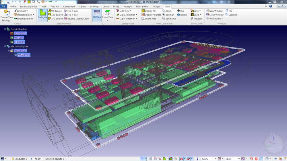
CR-8000 is an advanced 3D PCB subsystem development platform. It’s the ability to build and optimize complete PCB subsystems that include multiple boards, mechanical enclosure, power, and SI analysis. Utilizing the model architecture and requirements, CR-8000 can verify the proposed design meets model requirements before and during detailed design.
E3.series is an industry-leading wire harness and control panel design platform. Complex wire harness designs can be designed, visualized, and connected to manufacturing. Extensive design rule checks eliminate common errors. Integration with leading MCAD tools provides 3D analysis. CR-8000 PCB connector information can be directly imported.
E3.series Genesys Connector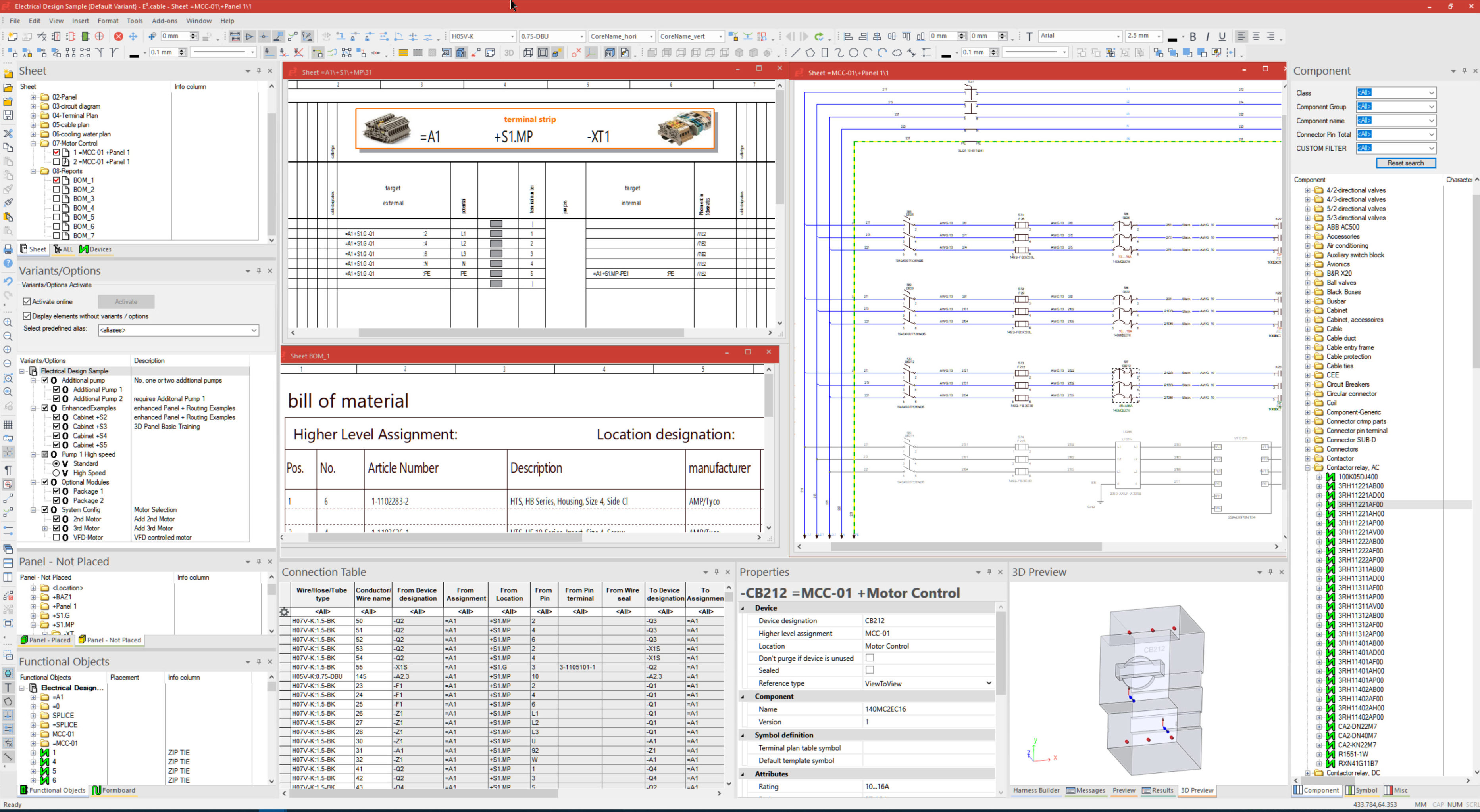
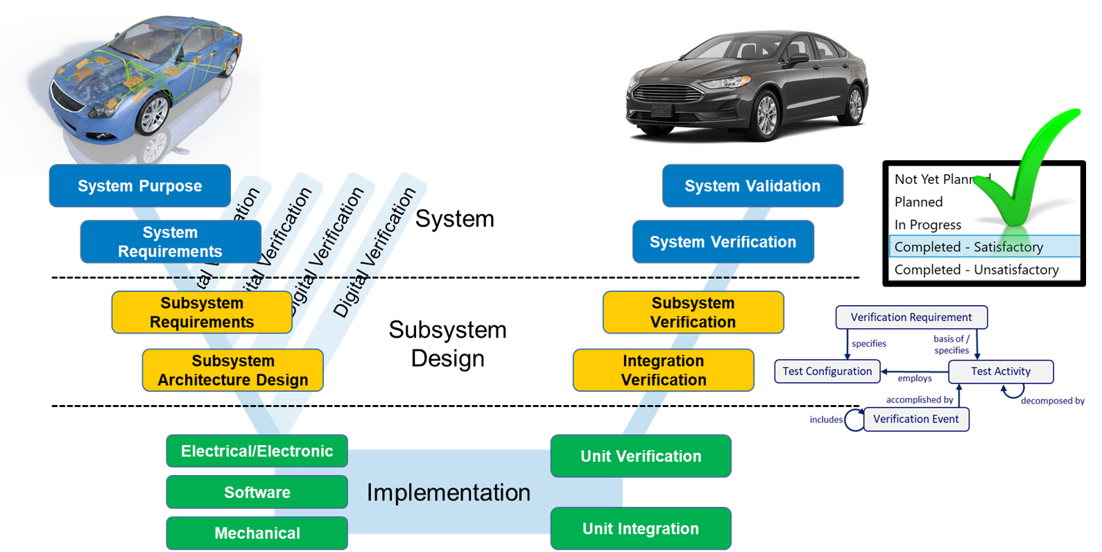
A critical part of E/E subsystem implementation is verifying requirements throughout the design process. GENESYS offers verification events that ensure model and implementation consistency. Verification gates would include architecture, design, and release to manufacturing. Verification alignment at the subsystem level adds convenience and efficiency.
Learn MoreModel-Based Engineering supports Digital Engineering methods. MBE utilizes a model-based approach as opposed to a document-based. The product model is used to drive wire harness and PCB detailed design.
The product model is constructed in GENESYS using system engineering methods. The product model or system context includes the product ecosystem. An example of the product ecosystem is the operating environment.
Model-Based Engineering supports a connected model design process. A model created in GENESYS is used to pass a design envelope to the development team for wire harness design and PCB design.
Model-Based Engineering provides product model access to diagrams, requirements, and parameters for viewing by the design team. The design team can access a particular component or subsystem.
Using the GENESYS Connector the component or subsystem architecture is directly transferred to E3.series for wire harness design. The design envelope is accessible providing diagrams, requirements, and parameters.
Using E3.series for wire harness design and CR-8000 for PCB provides 3D capabilities that are necessary for today’s complex designs.
GENESYS provides the ability to create verification events composed of verification requirements. Each verification event provides a design process checkpoint to assure model consistency with implementation. An example of a verification gate would be a design review prior to manufacturing.
Smart manufacturing and digital engineering are equal partners in digital transformation. Smart manufacturing depends on data that is gathered by IIOT and analyzed using big data. Providing the manufacturing floor with design data ready for machine consumption is an important output of MBE.
The Digital Thread is a foundational element of a successful Digital Engineering implementation. Digital conversations involving procurement, design, manufacturing and field service replace email and paper documents. Decisions and rationale are captured and provide traceability.
Digital Engineering requires a model-based design process that begins in Systems Engineering. Zuken acquired Vitech Corporation, a leader in Systems Engineering practices and MBSE solutions, with the intent of implementing an E/E model-based design process.