
Using Fixed Pi Attenuator for Estimated Cable Insertion Loss Simulation
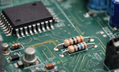
High-Speed cable for high-speed data transmission
The cable insertion loss margin represents the difference between the cable’s measured insertion loss and the maximum insertion loss level allowed per standards. The higher the margin, the better the cable performance.
Cutting it close when it comes to cable insertion loss margin doesn’t leave much wiggle room for cable temperature levels to rise without experiencing negative impacts. A simulation is necessary to estimate the cable insertion loss with advanced Tx/Rx buffer technologies and provide a visible margin against the standard,
This post introduces the concept of Pi attenuator and how to use the fixed Pi attenuator with IBIS AMI Tx/Rx models for estimating cable insertion loss simulations.
Fixed Pi attenuator and equations
Sometimes, the cable vendor does not provide the detailed cable model, such as s-parameter models, as most SI engineers recommend. Instead, the cable vendor provides only the insertion loss and impedance at a frequency point.
Fixed attenuators can have either equal or unequal impedances. They can provide any 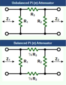 amount of attenuation (theoretically) equal to or greater than the configuration’s minimum attenuation–depending on the ratio of Z1/Z2. Attenuators with equal terminations have a minimum attenuation of 0 dB. Unequal terminations place a lower limit on the attenuation as follows:
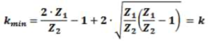
Expressed in decibels as:
![]()
In the attenuator formulas below, the linear attenuation ratio of the two powers or voltages (note that “k” has a minimum value if Z1 and Z2.are not equal).
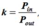
If, as is typical, the attenuation is given in decibels (K dB vs. k), then convert to a ratio as follows:
![]()
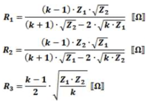
These equations apply to the two forms of Pi attenuators:
If Z1 = Z2, then:
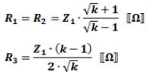
A fixed attenuator is a pure resistance device and is independent of frequency changes. We can use a fixed attenuator to model the cable insertion loss simulations.
Example: fixed Pi attenuator for insertion loss in eye diagram and IBIS AMI simulation
The task: Verify and determine if a 30 ft cable (15dB loss) gives enough margin for XAUI 3.125GHz signal
The knowns:
- The cable:
- low-cost differential high-speed cable. Zdiff = 90 ohm, 30 ft, 15.0dB insertion loss, @3.125GHz
- Generic XAUI device
- Driver and receiver
- IBIS AMI models
- Jitter
- Random jitter: 20% or 64ps @3.125G
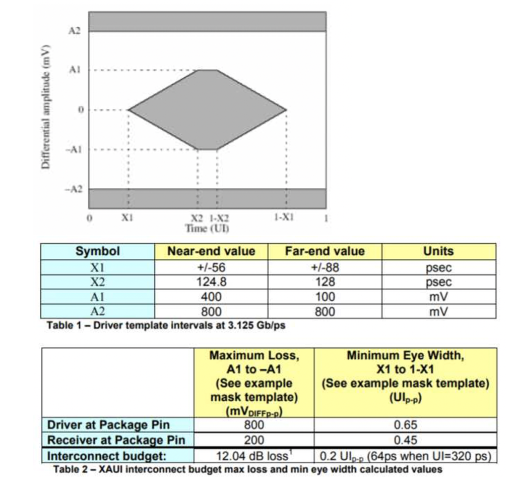
- Standard XAUI eye mask
Step 1: Build up fixed Pi attenuator in your topology editor and verify them for insertion loss value
- Calculate R1, R2 and R3 for different length cables (Use balanced Pi attenuator, Z1 = Z2 = 90)
- 30 ft, 15.0dB insertion loss, @3.125GHz
- k = 31.623; R1 = R2 = 128.92; R3 = 245.03; R3_a = R3_b = R3/2 = 122.51
- Build topology for the attenuator
- 30 ft, 15.0dB insertion loss, @3.125GHz
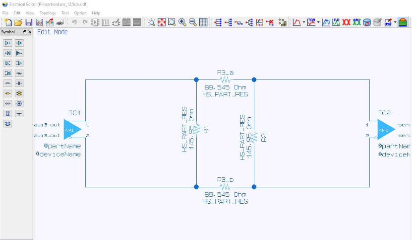
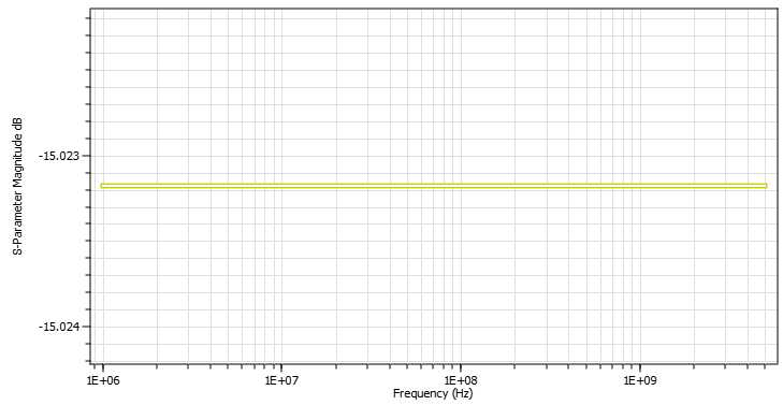
- Verify the insertion loss for these attenuators
- Measured insertion loss = 15.0232 dB
Step 2: Verify eye diagrams using simulations
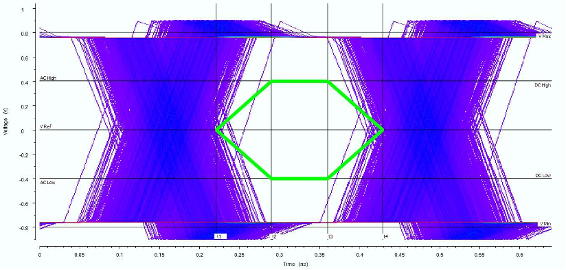
- Driver pin side-eye diagram with near side mask
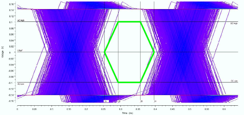
- Receiver pin side-eye diagram with far side mask
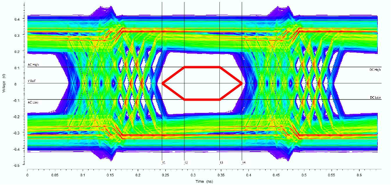
- Receiver out eye diagram with far side mask (AMI Simulations)
Step 3: the result
- Attenuator structure gives 15.0232 dB independent of the frequency changes. The method used is with 0.15% error only.
- At the driver pin, the attitude level is from 755 mv to -755 mv with 355 mv margin against the standard; the time eye open is 164 ps (maximum) with -44 ps margin against the standard.
- At the receiver pin, the attitude level is from 141 mv to -141 mv with an 82 mv margin against the standard; the time eye open is 167 ps (maximum) with 23 ps margin against the standard.
- Use XAUI AMI models with the default mode; the AMI simulations give the result as:
- At the receiver output, the attitude level is from 182 mv to -182 mv with 164 mv margin against the standard; the time eye open is 159 ps (maximum) with 15 ps margin against the standard (receiver pin mask).
Conclusion
In actual designs, we can use the attenuator method for modeling the insertion loss. The fixed Pi attenuator can give an accurate passive insertion loss as we expected. By using this method, the regular eye diagram simulation can be performed for estimating the margins against the standard. Furthermore, the IBIS AMI simulations can be used to estimate the effects of algorithms in XAUI devices (FFE, DFE, AGC, CTLE, etc.).
References:
- Wiki page of Attenuator https://en.wikipedia.org/wiki/Attenuator_(electronics)
- com Fixed Pi and Tee Attenuators – Equations https://www.rfcafe.com/references/electrical/attenuators.htm
- Designing with Samtec high-Speed Cable Assemblies http://suddendocs.samtec.com/notesandwhitepapers/designing%20with%20high%20speed%20high%20density%20cable%20assemblies%200305.pdf
- DP Array™ DPAM/DPAF Final Inch® Designs in XAUI Applications
http://suddendocs.samtec.com/notesandwhitepapers/app10_xaui_dpax.pdf
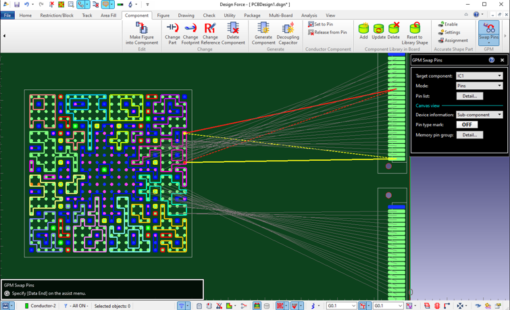
- Zuken Design Force – Analysis Module 2020: Electrical Editor, Analysis Result Viewer

- Blog

- Blog
- Blog

- Blog
Related Products & Resources
- Products
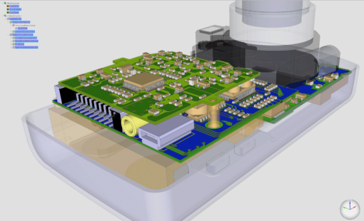
Zuken reveals details of release 2020 of its advanced 3D multi-board EDA environment CR-8000.

- 2020 Technical Webinars
This webinar will explore a high-speed design process in CR-8000 that utilizes a constraint browser, topology template, crosstalk estimation, signal and power integrity simulations.
- Products
Design Force combines traditional 2D design with native 3D design and the latest human interface techniques, accelerated graphics and almost instantaneous rendering and refreshing. It is the fastest, most effective PCB design solution available today. Design Force enables design teams to layout their designs in the context of a complete system or product.

- Products
Building a competitive product today is much more difficult than a few years ago. Existing PCB-centric design processes are limited to a single PCB and do not provide the necessary tools for today’s competitive product development environment. PCB-centric design processes are falling behind.