Circuit Diagram Design: A Practical Guide for Modern Engineering Teams
Introduction
Circuit diagram design sits at the heart of every electrical program. For leaders accountable for throughput, quality, and compliance, clear diagrams shape outcomes across planning, manufacturing, and service. As systems become more complex and teams spread across multiple locations, accurate and readable documentation becomes a key lever for reducing risk, shortening lead times, and protecting margins. Strong diagrams cut rework, prevent miscommunication, and support digital continuity across the product lifecycle.
Why Circuit Diagram Design Matters
Good diagrams reduce project and business risk. Poor or outdated diagrams trigger build errors, service delays, and compliance issues that inflate costs. Accurate documentation improves communication, manufacturability, safety, and troubleshooting. It also accelerates engineering change cycles by keeping intent and implementation synchronized.
Business outcomes
- Higher first‑pass yield and fewer line stoppages
- Faster ECO cycles and shorter engineering lead time
- Lower warranty cost and mean time to repair (MTTR)
- Consistent, audit‑ready documentation for compliance
- Clear communication with suppliers and contract manufacturers
Types of Circuit Diagrams (and When to Use Them)
- Schematic diagram shows the electrical function and how the components connect. Use it for planning, simulation, and PCB design reviews. It is the primary source for logic and connectivity.
- Wiring diagram shows wire routing, device placement, and installation details. Ideal for manufacturing, harness build, and field service. It translates intent into concrete build steps.
- Block diagram provides a high‑level view of subsystems and their interactions. Use it to align architecture and communicate scope with stakeholders.
- Pictorial diagram depicts components with drawings or photos. Helpful for training, service manuals, and quick identification.
How to Read Circuit Diagrams with Confidence
A simple, repeatable approach improves accuracy:
- Identify the power source and protection.
- Trace the main current path from source to load.
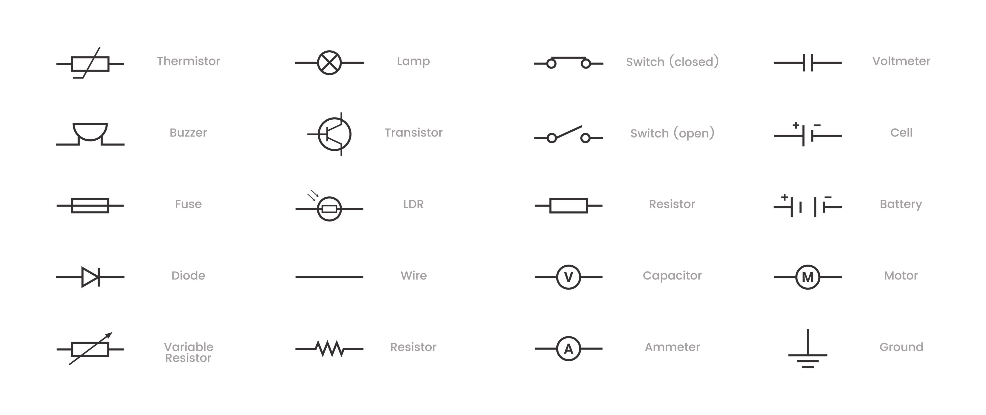
- Recognize each symbol and confirm values.
- Review labels, reference designators, and cross‑references.
- Look for branches, connectors, and terminations.
- Confirm the return path or ground scheme.
Use page zones and signal references to follow nets across sheets. If something looks odd, check for missing connection dots or unintended jumps.
How to Create Clear, Accurate Circuit Diagrams
Follow these steps to improve consistency:
- Define the goal and operating conditions of the circuit.
- List required components and approved part numbers.
- Use software with a controlled symbol library and naming rules.
- Draw the main path first; then add branches and interconnects.
- Add labels, wire types, and reference designators.
- Review with peers and manufacturing. Fix clarity issues early.
Quality checklist
- Title blocks and revision data are complete.
- Symbols comply with IEC/IEEE standards.
- Connection dots and no‑connects are unambiguous.
- Cross‑references and sheet zones are correct.
- Wire types, gauges, and colors are specified where needed.
- Notes include safety, test, and torque requirements.
How Modern Design Tools Improve Circuit Diagram Design
Engineering teams need tools that support accuracy, automation, and collaboration. Zuken’s platforms strengthen each stage of circuit diagram design.
E3.series for Electrical and Wiring Design
E3.series supports electrical wiring, control systems, and panel design. It creates intelligent diagrams that update automatically as designs change.
Benefits
- Reduce release defects with real‑time rule checks
- Generate BOMs, wire lists, and from‑to tables automatically to save hours per release
- Enforce standards with governed symbol and component libraries
- Enable parallel work with controlled permissions and design rules
- Maintain a single source of truth across schematics, wiring, harness, and panels
These capabilities shrink rework and handoff delays. When a device or wire changes, downstream drawings and reports update together to protect the schedule.
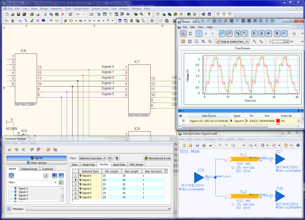
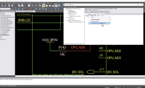
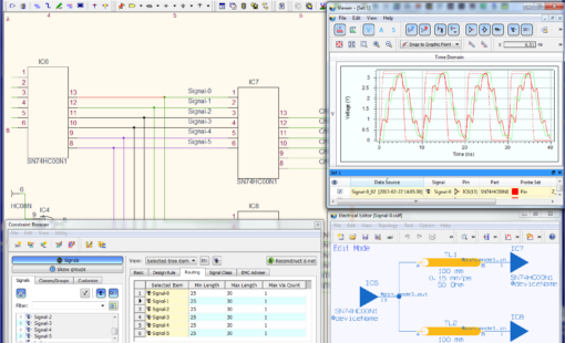
CR‑8000 for PCB and System‑Level Design
CR-8000 streamlines the transition from schematics to PCB layout and enhances system-level accuracy.
Benefits
- Manage constraints early to prevent late re‑spins
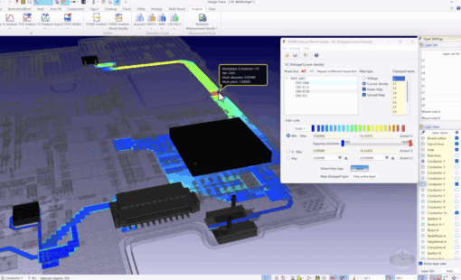
- Coordinate ECAD‑MCAD in 2D/3D to avoid fit issues
- Apply signal integrity and EMI analysis to reduce field risk
- Plan multi‑board, multi‑domain systems without data silos
With CR‑8000, electrical and mechanical teams share a common context. That alignment reduces iteration loops and protects the total cost of ownership.
Conclusion
Circuit diagrams remain essential to effective electrical system design. For decision‑makers, improving circuit diagram design is a practical path to lower risk, higher yield, and predictable delivery. With intelligent tools like E3.series and CR-8000, organizations improve accuracy, reduce errors, and strengthen their digital engineering foundations.
Next Steps
- Explore the E3.series and CR‑8000 product pages to review capabilities.
- Contact our team for a workflow assessment focused on cycle time, quality, and compliance.
—
Related Reading

-
Manager of Engineering Operations, SOZO Center at Zuken USA Inc.


- Blog

- Blog

- Blog
- Blog
Related Products and Resources
- Blog

- Products
- Products
PCB Design Creation - Design Gateway is a platform for logical circuit design and verification of single and multi-board system-level electronic designs. It supports a true system-level circuit design in which individual circuits can be represented and connected as blocks.

- Blog