Tech-Tip: Managing Variants, Part 1
The benefits of variants:
The primary benefit of using variants is to reduce the variety of physical parts to fabricate and inventory, such as bare printed circuit boards. Managing variants can also reduce the number of design and manufacturing artifacts that engineers need to create and maintain. A product line can utilize shared artifacts instead of multiple copies. CAD applications–schematic, layout, parts lists–manage and share variant data to minimize data re-entry time and potential errors. Then, these applications present data to the user in different views and outputs to meet a variety of needs depending on the user’s role.
Intro to product variants
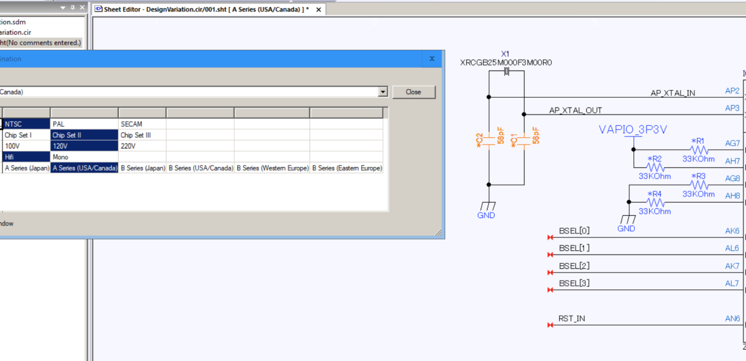
An electronic product design can have several options to suit different design requirements. For instance, a TV could have different power and video standards to suit varying target markets or destinations. A single set of design and manufacturing artifacts might define a range of product options, specifying the differences, or variants, where applicable. A variant might be part substitutions, or potentially whether or not to use a specific part such as a no-mount. There may be several variants for a given destination. The image below shows destinations listed in the left column with their variant values defined to the right.

Variants add a level of complexity requiring multiple design and manufacturing artifacts that are similar, but unique to address the variety of product options used to address different market requirements.
Defining variants in Design Editor
Now that you’ve had a brief intro, next let’s look at how to set up a schematic to use variants, how to add variant information to parts, and the visualization aids within the Design Editor.
You will use two resource files with variants:
- Specifies Destinations and Variants: …\resource\data\vmdata.rsc
- Specifies Properties that can vary by component function type: …\resource\rule\vmprop.rsc
- The video covers how these are accessed from within Design Editor.
The image below shows how a user can specify that variants will be used when creating a new schematic.

If the user includes an existing, non-variant schematic with the variant features, Design Editor will prompt them to enable it.
To assign a variant to one or more parts, select the parts and use the Design Assist feature as shown in the image, below. The Component Browser sets the part numbers–or no mount status–by variant type. We’ll cover that in the video, too.

An asterisk on the reference designator indicates variants, and colors differentiate variant types. For example, in the image below, the voltage variant is orange, and the audio is blue.

The video below shows how to define and use variants in the Design Editor.
Variants have several benefits, but take some planning and organization to implement. However, with a robust schematic capture application, managing the data to make variants can be less burdensome to implement and maintain. My next post will show how to use this information in the Component List Master, one of the DS-CR ePDM modules.
Read more of our Tech-Tips here!

-
Application Engineer for DS-2/CR/OP

- Blog

- Blog

- Blog

- Blog
- Products
PCB Design Creation - Design Gateway is a platform for logical circuit design and verification of single and multi-board system-level electronic designs. It supports a true system-level circuit design in which individual circuits can be represented and connected as blocks.

- Products
Building a competitive product today is much more difficult than a few years ago. Existing PCB-centric design processes are limited to a single PCB and do not provide the necessary tools for today’s competitive product development environment. PCB-centric design processes are falling behind.