
Tech Tip: How to Create an E3.formboard Component Symbol for Non-Connector Devices
Not every component in a harness is a connector or wire. As harness designs incorporate varied end-line devices, engineers must properly capture these components to support accurate manufacturing documentation.
Creating an E3.formboard component symbol allows non-connector devices to display correctly and maintain proper connectivity in manufacturing documentation. This tech tip explains how to model these components so formboards reflect both the physical device and the wiring defined in the schematic.
What Are Non-Connector Devices in Harness Design?
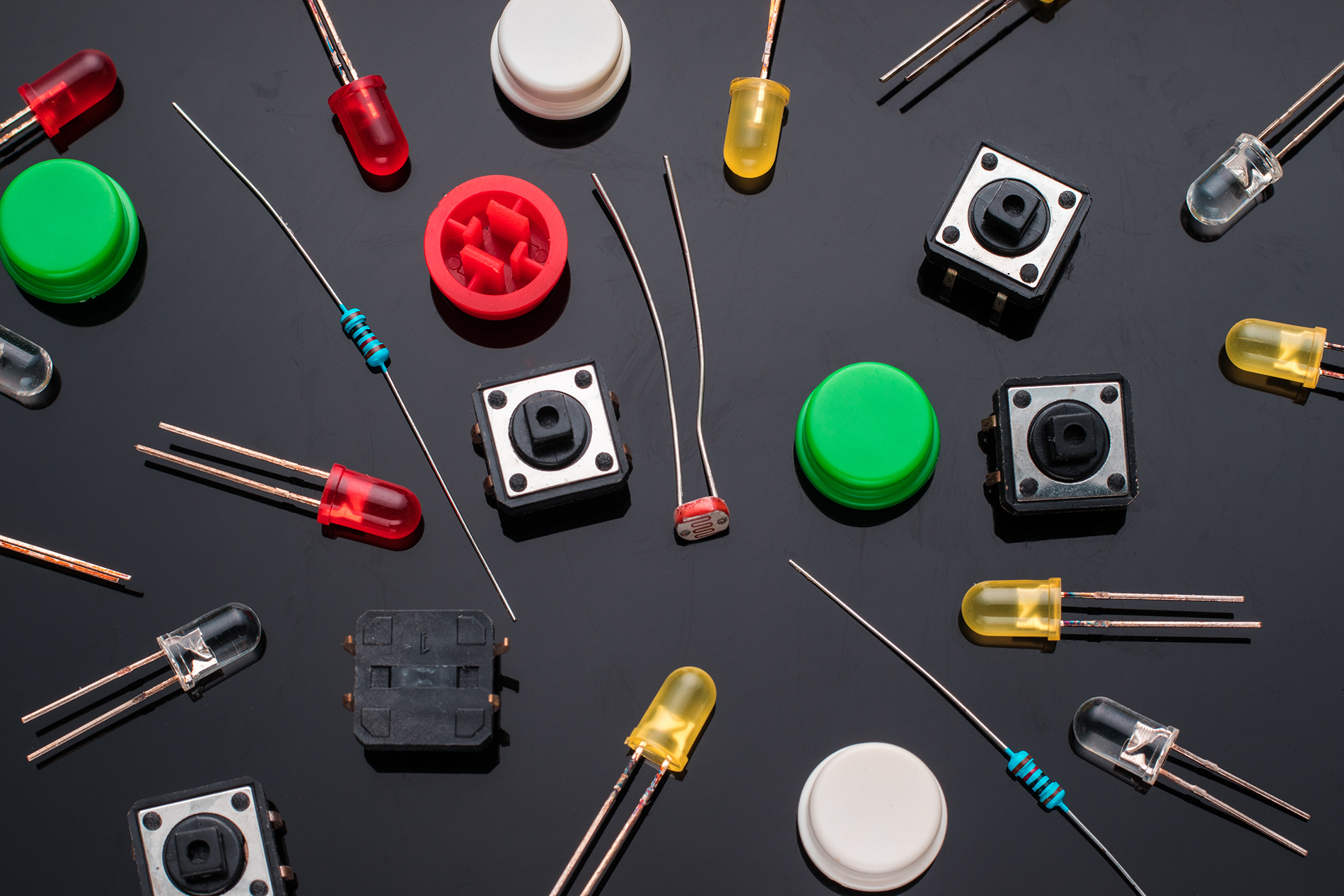
A non-connector device is any component in a harness that terminates a wire but is not a connector. In this context, these are end-line components such as switches, relays, sensors, or inline modules that exist physically on the harness and perform a functional role in the system.
This definition does not include harness accessories like backshells, coverings, or contacts. While those elements are part of the harness assembly, they do not act as functional electrical endpoints.
Why Non-Connector Devices Are Becoming More Common in Harness Design
Modern harness designs are becoming increasingly complex. Vehicle and electrical systems engineers now place more functionality directly on the harness using switches, sensors, relays, and inline modules.
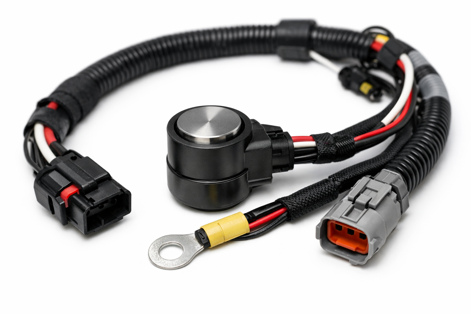
Installation requirements also push engineers to pre-wire these components into the harness. This approach simplifies assembly and streamlines installation during subsystem integration.
This shift increases the need to accurately represent non-connector devices in manufacturing outputs such as harness formboards, where documentation must match real-world assemblies.
Why Non-Connector Devices Require a Specialized E3.formboard Component Symbol
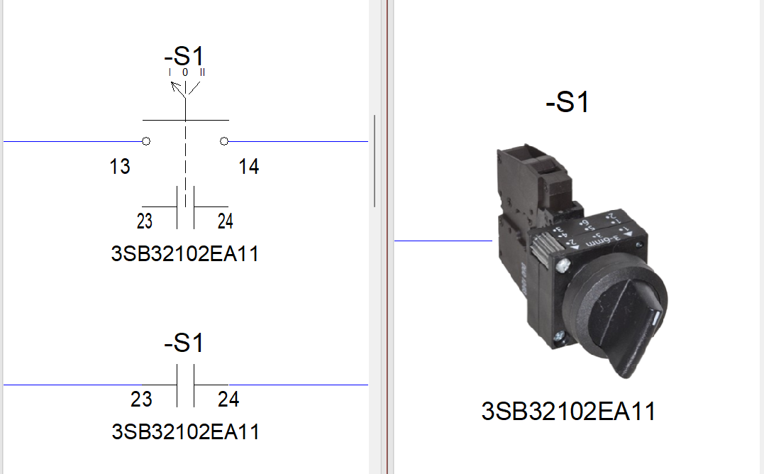
Harness designers use E3.formboard to create manufacturing drawings that technicians can follow during assembly. Formboards do not use schematic symbols because they do not reflect the physical device. Instead, best practice is to use physical representations—such as side views, face views, or images—so technicians can clearly identify what to place on the board.
E3.formboard users also need to model non-connector devices correctly to take full advantage of the automation built into the E3.series design suite. Engineers must define these components so:
- Connection lines attach correctly
- Wiring defined in the schematic transfers automatically to connector tables
- The E3.formboard component symbol graphically reflects the device
Modeling non-connector devices this way ensures the formboard is both visually clear and electrically correct, reducing ambiguity during assembly and improving build quality and speed.
How to Create an E3.formboard Component Symbol
Creating an E3.formboard component symbol involves defining a specific symbol in the database and linking it to the component.
The video below walks through the following steps:
- Importing symbol graphics
- Defining connection points, including a critical step
- Mapping the symbol to the component
- Grouping pins so the formboard symbol captures all wiring
Watch the video below for a step-by-step demonstration.
Who Should Use This Approach?
Harness Designers
When to use: When defining harness connectivity that includes end-line components like switches, relays, or sensors.
Benefit: Ensures wiring transfers correctly between the schematic and the formboard, reducing rework between design and manufacturing.
Library Administrators
When to use: When creating or maintaining component definitions used across multiple harness projects.
Benefit: Standardized formboard component symbols improve consistency, reduce errors, and support scalable library management.
Formboard Engineers
When to use: When generating manufacturing drawings that include non-connector devices on the harness.
Benefit: Improves visual clarity and ensures the formboard reflects real-world assembly requirements.
This helps engineers easily spot invalid nets and quickly reassign nets to areas, keeping the PCB layout aligned with the latest schematic.
Conclusion: Ensure Accurate Harness Representation with Proper Component Symbols
As harness designs evolve, non-connector devices play a more active role in both system functionality and physical assembly. Modeling these components correctly in E3.series ensures they appear accurately on the formboard and maintain proper connectivity from schematic through manufacturing.
Using dedicated E3.formboard component symbols improves clarity for technicians, preserves design intent, and reduces errors during assembly.
Next Steps: Learn more about harness design with Zuken
The video below walks through the following steps:
- Visit: Harness design software product page
- Read: IPC-D-620 compliance with Zuken
- Read: Tips for series library automation
- Watch: Introduction to Harness Builder for E3.series

-
Senior Applications Engineer


- Blog
- Blog
- Blog
- Blog
Related Products and Resources
- Blog
- Blog
- Blog
- Blog