5 Steps to More Effective Mechatronic Cable Design (Part 1)
If you’re an electrical engineer, you’ve most likely thought about the benefits to the design process if you were to collaborate with your Mechanical Engineering counterparts, or perhaps you are already looking into which areas you could collaborate on for a better Mechatronic cable design process?
In this first (of two) posts I will look at three, of five, key functional areas you can improve to make your cable design process more effective.
- Defining Cable Sizing
- Calculating Bend Radii
- Selecting Additional Parts
- Route Optimization
- Manufacturing
Why bother collaborating electrical & mechanical design?
You already know this, but I’ll say it anyway.
If you want to minimize errors associated with cable management, it is critical to design and manufacture an effective solution from the onset…
…and one that can be efficiently maintained and easily replicated when required. “Yeah, yeah, yeah…but really, how do I do this?”
Well, the smartest method involves full collaboration between the electrical and mechanical departments.
– You can use what follows as guide to go to your seniors and convince them of the value. I’ll carry on…
By working together, the earliest revisions of a design will reflect the logical world of the electrical engineer, while taking into account the three dimensional world of the mechanical engineer. This minimizes redesign after the initial prototype stage and delivers a much higher quality product, all in less time and without waste. Who can argue with that?
There are five functional aspects of an electrical system design where you, as an electrical engineer, should consider collaborating with mechanical engineers. Below is a guide to how you can both work together for a more refined result.
1. Defining Cable Sizing
The risk of motor burn out or wire disintegration that results from exceeding current capacity has a very real and dangerous impact – it’s not just about reliability but also the safety of a product.
It is critical to size cabling accurately, and done up front in the early part of the design process, by collaborating with mechanical department, you can save a lot of time and rework.
By having the physical 3D design data on hand, you will know that it is possible to identify:
- if a wire is too big for a connector
- if it is long enough to accommodate passing through a bulkhead, for example, and then allow for detours around physical obstacles.
As we all know, without this key length information the size (and associated resistance) can only be defined through guesswork, or later at the prototype stage with a piece of string and a ruler.
– Those were the days…
2. Calculating Bend Radii
The bend radius measured to the inside curvature is the minimum radius that a cable can be bent without kinking it, damaging it, or shortening its life.
The problem that you face is that electrical design systems do not account for bend radii because the designs are not illustrated within the physical 3D world. However, mechanical systems do – and together they not only determine the bend radius, but are also capable of showing when the minimum bend radius has been exceeded. Because this happens early in the design phase it eliminates later problems.
The undesirable alternative is to wait until the prototype phase and go back to the old school methods of using a protractor to measure every dubious looking curve within the design.
3. Selecting Additional Parts
The physical 3D world has a massive impact on what additional parts are selected and incorporated into any cable design, whether it is a plug, socket, backshell or insert, each part needs to be compatible with the cable and the connector.
Without mechanical collaboration the design can only be completed on a flat single dimension sheet resulting in the use of a straight backshell for example, the reality could be very different – space issues may mean that the only way a design can be realized is to utilize all the space dimensions and could call for a 45 or 90 degree backshell.
Further Information
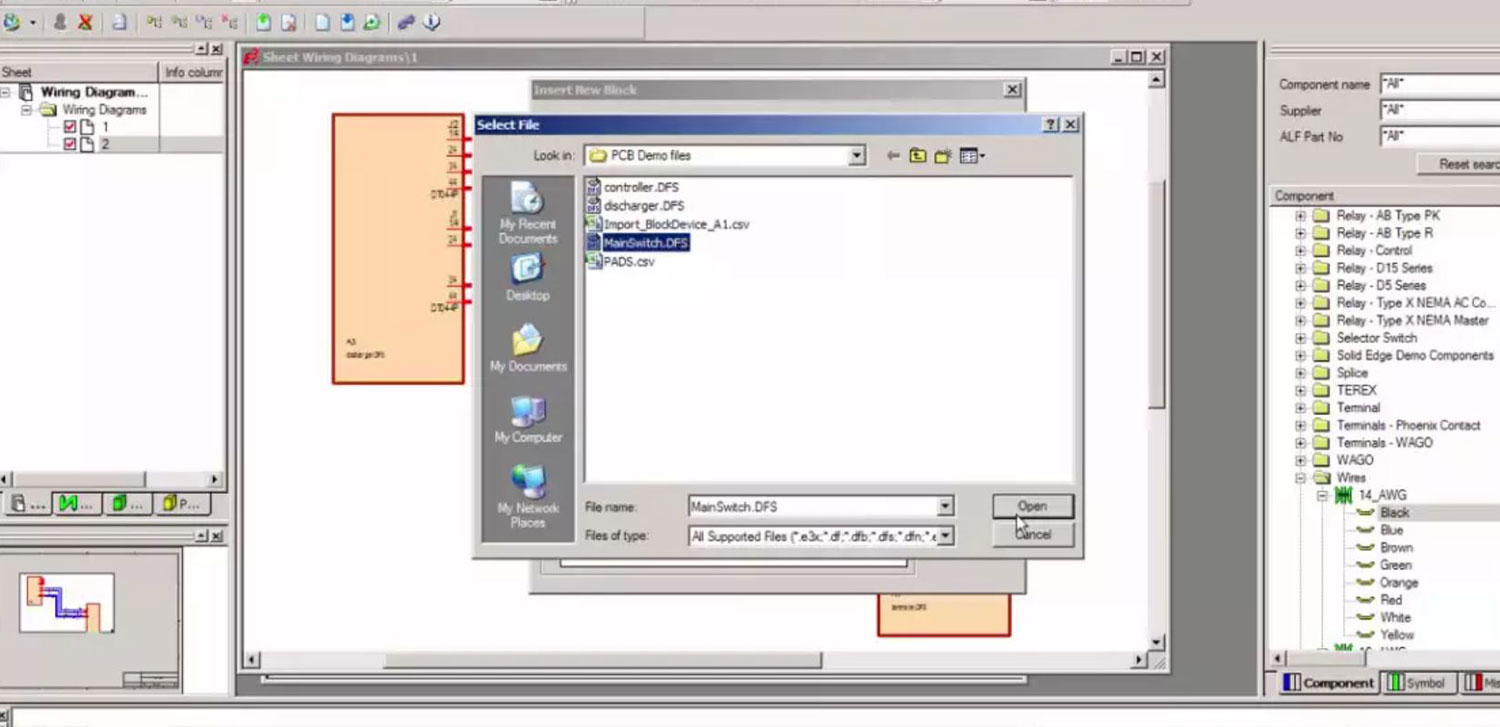
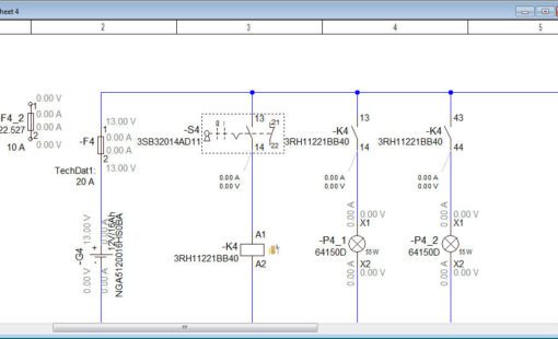
That’s all for this week, but if you would like more details on a product that can do all of this and more then check out our E3.series, Electrical CAD software for cabinet layout, electrical and wire harness design – and in particular – E³.cable.
We also have an OnDemand webinar available for more Mechatronic collaboration design tips.
- On Demand Webinar: Streamlining Electrical System Design through Mechanical & Electrical Collaboration
Below is a 2 minute preview of what to expect within the webinar, or select the link above to access the full 40 minute webinar, including software demonstration.

- Blog
- Blog

- Blog

- Blog
Related Products and Resources

- Test Drive

- Products
- Products

- Products
E3.series is a Windows-based, scalable, easy-to-learn system for the design of wiring and control systems, hydraulics and pneumatics. The out-of-the-box solution includes schematic (for circuit and fluid diagrams), cable (for advanced electrical and fluid design), panel (for cabinet and panel layout), and formboard (for 1:1 wiring harness manufacturing drawings). Integrated with MCAD, E3.series is a complete design engineering solution from concept through physical realization and manufacturing output.