
IPC-D-620 Standards Compliance with E3.series
IPC-D-620 is a standard developed by dozens of leading experts in cable and wire harness design and manufacturing. The standard provides guidance to accomplish the following:
The design of electrical wiring harnesses and cable assemblies shall be based on the known worst-case operational requirements and expected use. These include, but are not limited to: assembly processes, shipping and storage; installation; test exposure; service environment (operational temperature limits, mechanical, thermal, and vibration stress; contamination; corrosives; EMC/EMI/RFI, ionizing / non-ionizing radiation, moisture or other fluid media exposure); post-use test and data recovery; and life expectancy. [1]
After some friendly conversations with our partners at IPC and WHMA, I decided to review the IPC-D-620 document to see how it relates to Zuken.

After a few hours and several cups of coffee, here’s what I found about how E3.series can help you stay in compliance with IPC-D-620.
System Definition
System Requirements Specification (SyRS)… describes and defines the requirements, and verification of those requirements, for a combination of elements that must function together to produce the capabilities required to fulfill a mission need, including hardware, equipment, software… [2]
A wire harness engineer starts with understanding the system context. The IPC-D-620 provides guidance on the type of information the harness engineer needs to start, including interface control drawings (ICD) to describe subsystems, performance and reliability standards, and system requirements. These documents define a design envelope and context from which the harness engineer designs the wiring to connect the entire system.
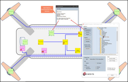
Using E3.series and GENESYS, the systems engineer can relay SyRS requirements directly to electrical engineering using a digital thread. This integration directly exposes requirements, diagrams, and system context within the electrical design tool. Additionally, E3.series can directly ingest ICDs in the IPC-2581 format or .csv file, ensuring accurate data transfer between subsystem teams.
Physical Construction and Installation
Cable and wiring harness assemblies shall be designed with features that contribute to the ease and rapidity of maintenance without removal of other equipment, interconnections, wire bundles, and/or fluid lines [3]
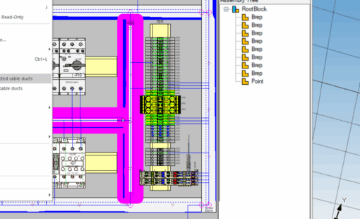
Section 3.2.2.2 is one of many sections of the IPC-D-620 detailing considerations for the wire harness’s physical layout. Engineers model the system in 3D mechanical software to account for considerations like installation ease and bend radius. E3.series exchanges critical data into 3D MCAD software. After importing electrical components into the physical model, the harness engineer routes and verifies that the harness’s path meets design standards.
Section 6 of the IPC-D-620 details requirements for terminations, splices, wire lay, and assembly details. Here are several examples of how E3.series can help.
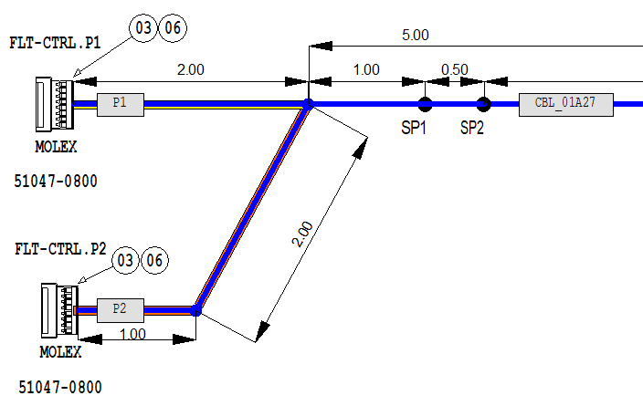
- Section 6.1.1 requires splices to be spaced evenly. E3.formboard visualizes splice placement and easily documents exact placement along a segment.
- Section 6.4 recommends a helical twist for harnesses with four or more cables. Harness Builder for E3.series automatically calculates the wire cut length to accommodate the additional length.
- Section 6.9.1 states that harness assemblies must be clearly marked. With a single click, the cable engineer can automatically size and place labels for connectors and cables.
Designing cables that meet the dozens of harness construction rules can be difficult. Zuken’s tools can automate compliance.
Safety and Reliability
The standards in the IPC-D-620 ensure the system reliability and the safety of those who use it. For example, for wire selection, it states
Selection of wire and cable shall take into account of all requirements of this specification and the following design considerations… sizing, strand count, construction, material, coating, count, electrical, temperature, mechanical, outgassing, shielding [4]
Section 4.8 lists a myriad of characteristics when selecting wires. Other sections describe similar considerations for connectors, contacts, shields, and accessories. It’s critical to choose parts that fit the operating context. Engineers need help sifting through choices to pick parts with the proper characteristics.
E3.series stores these characteristics in a component database. The engineer can filter for the material, temperature range, or any other characteristic and pick the proper part number for the job.
Ensuring electrical reliability is crucial for maintaining the integrity of electrical systems. High and low voltage lines must be separated to prevent EMI in sensitive low voltage control signals. Shielding prevents leakage or arcing. Improper grounding can lead to signal interface, or worse, could result in electric shock or even fire. Multiple standards throughout the IPC-D-620 provide a framework for engineers to consider when designing their system.
E3.series helps engineers design safe systems. Signal tracing helps engineers check ground paths. Cable protection can be automatically selected. Shielding paths can be exported for analysis. Pin layouts can be generated to understand which wires are going to which pin. While not everything can be automated, computer-aided design clearly displays information to help engineers make sound, informed decisions.
Documentation
The documentation package should consist of multiple pieces of information that fully describe the characteristics and functional performance requirements of the hardware… schematic diagrams, assembly descriptions, fabrication data, wire lists, test requirements. [5]
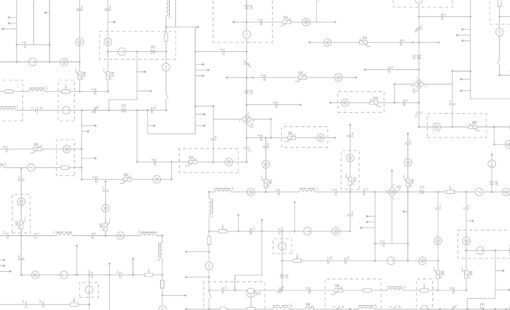
Section 8 of IPC-D-620 details the documentation that engineers must deliver to manufacturing. With E3.series, engineers can create schematics and diagrams, then automatically generate the wire list and tester scripts. Rather than building separate files, they generate all artifacts from one synchronized model. This approach saves time and reduces errors while still meeting documentation standards
Conclusion
The IPC-D-620 was a lengthy, dry, challenging read, but it was also incredibly educational and interesting. Despite spending my entire career in the industry, I learned something new on nearly every page. With so much content, it’s difficult to expect anyone to memorize it all.
Fortunately, you don’t have to. E3.series helps you design wire harnesses that align with IPC-D-620 standards. Features like automated error checking, generative documentation, and cross-discipline integration help you design with confidence, efficiency, and clarity.
If you’re curious about the full scope of IPC-D-620, you can order your own copy here. If you’re ready to streamline compliance and improve design quality, explore what Zuken can do for you.
References
| [1] | IPC-D-620A: Design and Critical Process Requirements for Cable and Wiring Harness Assemblies, 2021, pp. 8, section 3.1. |
| [2] | IPC-D-620A, pp. 9, section 3.2. |
| [3] | IPC-D-620A, pp. 10, section 3.2.2.2. |
| [4] | IPC-D-620A, pp. 17, section 4.8. |
| [5] | IPC-D-620A, pp. 33, section 8. |

-
Application Engineer


- Blog

- Blog

- Blog
- Blog
Related Products and Resources
- Blog

- Blog

- Webinar