IBIS EBD Model Verification for Reliable Design Analysis
The Need for IBIS EBD Model Verification
Modular design has become more prevalent in recent years. Often, it serves as design reuse for some complex applications, such as IoT sensors, memory modules, switching boards, display cards, etc. However, due to the increasing speed of digital signals, modular boards require simulation for system verification and analysis. This brings a challenge for IP protection, as the simulation setup requires detailed information about the module layout geometry and chip connections. An IBIS EBD (Electrical Board Description) model provides the connections and electrical net characters between pins and components. It also links with IBIS buffer, package, and connector models in the EBD.
What is IBIS Modeling?
IBIS (I/O Buffer Information Specification) is an industry standard for modeling I/O buffers and high-speed interconnects, focusing on performance, IP protection, and interoperability. In April 1997, IBIS EBD was added to the IBIS Specification (BIRD36.6). The inception of IBIS EBD addressed the challenges of simulating module boards for system designs. However, it was not widely accepted until the invention of the DDR2 module around 2003.
The IBIS EBD model includes three main sections of the board information:
- [Pin List]: Defines the pin names of user-accessible pins. It also defines which pins connect to which signals, including power and ground.
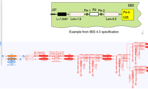
- [Path Descriptions]: the net information from the board. It can include the components in the ends, trace characterizations, connections, etc.


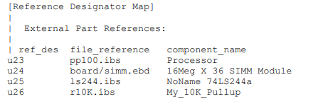
EBD Path Description format - [Reference Designator Map]: Listed RefDes with IBIS file and component name. All IBIS files referenced here must be in the same folder location as the EBD file.

EBD RefDes format
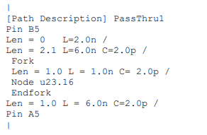
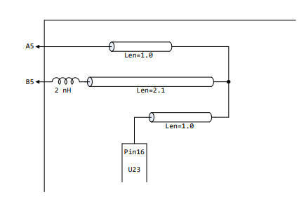
IBIS EBD has complexity as it represents a module board. As you can imagine, the most complicated part is the [path description] since it is in text format, not an image. It is hard to imagine a picture by just reading a text file.
Steps for IBIS EBD Model Verification
Before using it in a simulation, properly checking and inspecting the IBIS EBD model is essential. Those are tasks that robust EDA tools should be responsible for managing. As an example, let’s use Zuken’s CR-8000 Analysis Module to see how an EDA tool can work on IBIS EBD models.
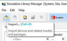
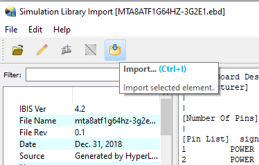
Step One: Importing the IBIS EBD Model
Zuken’s CR-8000 Simulation Library Manager (SLM) is a centralized repository for simulation models. Every model used in the simulations must be loaded into the Simulation Library Manager.
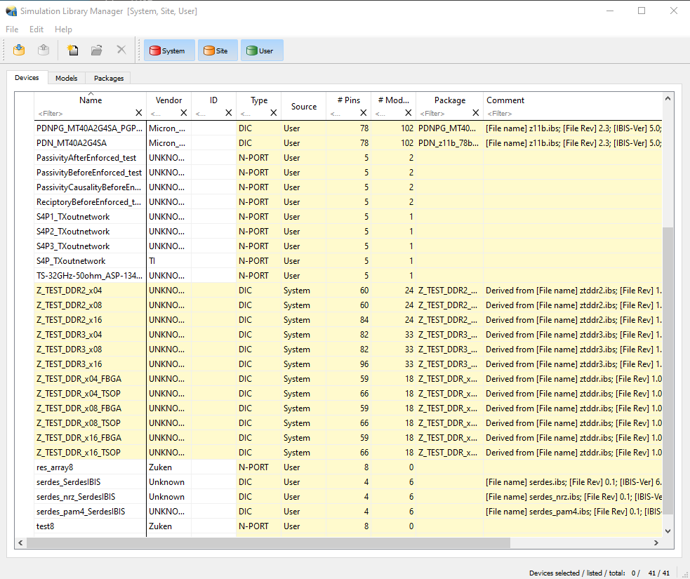
Simulation Library Manager Interface
- Click the Import button to select an EBD model to add to the SLM.
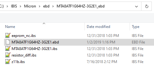
- The SLM will load the EBD file and the referenced “.ibs” and “.pkg” files in the same directory. In the loading process, the SLM also calls the latest IBISCHK (IBIS Golden Parser developed by IBIS Open Forum) and displays messages for Notes, Warnings, and Errors. The SLM will not allow “Import” to continue if there is an error in the parser message.
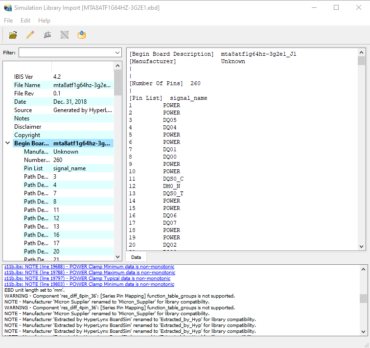
- After clearing all ERROR message(s), click the “Import” button to finish the process.
- The IBIS EBD model and all referenced models are now imported into the SLM.
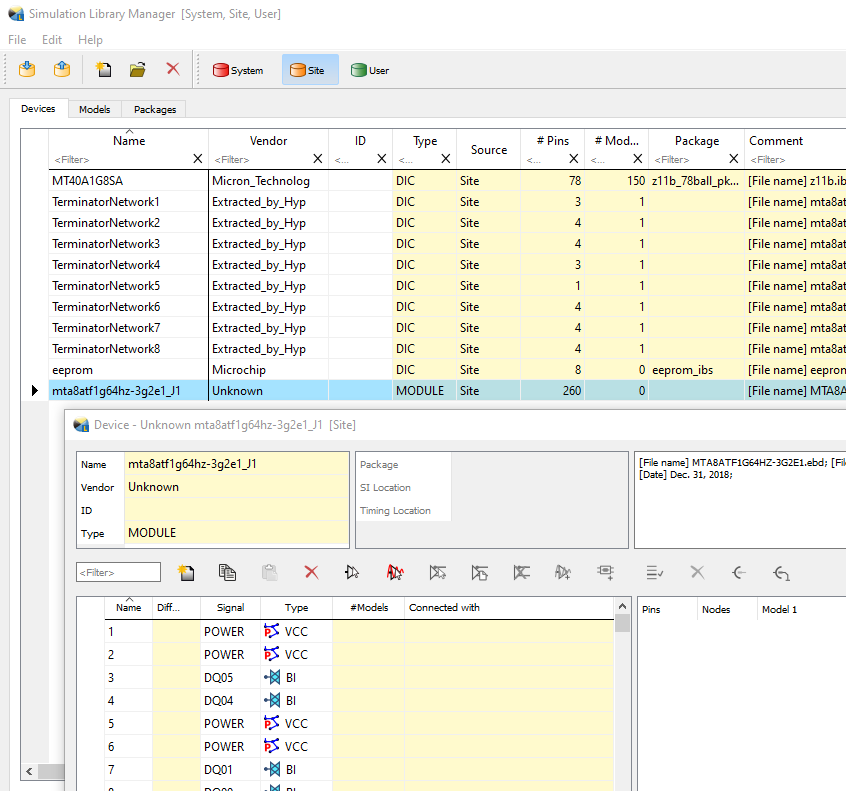
- The benefit of this import process is to check the EBD model with the IBIS Golden Parser and SLM software. This automated process also finds all the referenced models and loads them into the SLM (which is also checked). At this point, the IBIS EBD model verification process is ready for simulations.
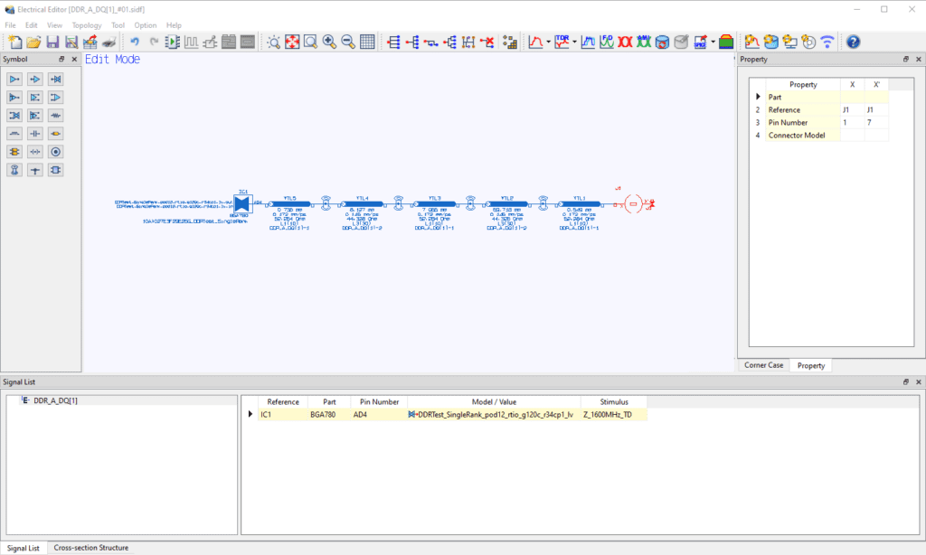
Step Two: Initiating the IBIS Simulation
Now that we have all the EBD-related information in the SLM let’s put it in the simulation.
- First, start Zuken’s CR-8000 Analysis Module Electrical Editor. An E-net is placed and ready to connect with the IBIS EBD through J1.
- Next, right-mouse-click J1 and select “Connect Module…”.
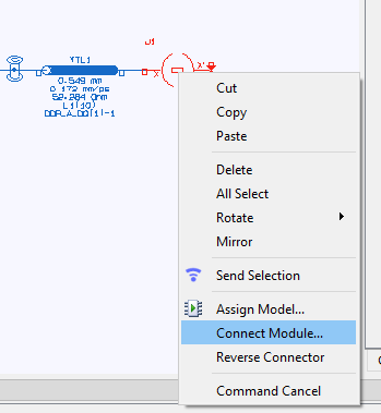
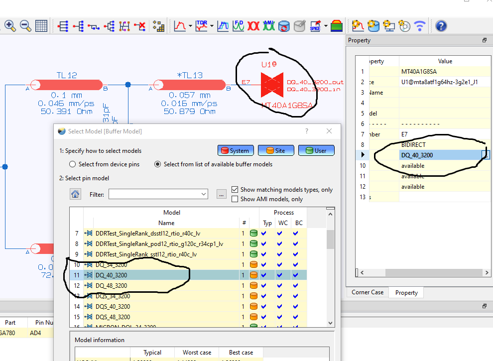
- Now we can get a connector pin from the IBIS EBD model. Let’s connect with Pin 7.
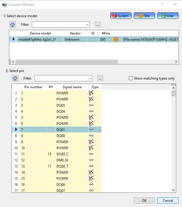
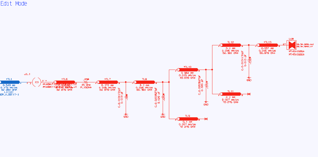
- After we click OK, the Electrical Editor shows the graphical connections in the EBD model in RED.
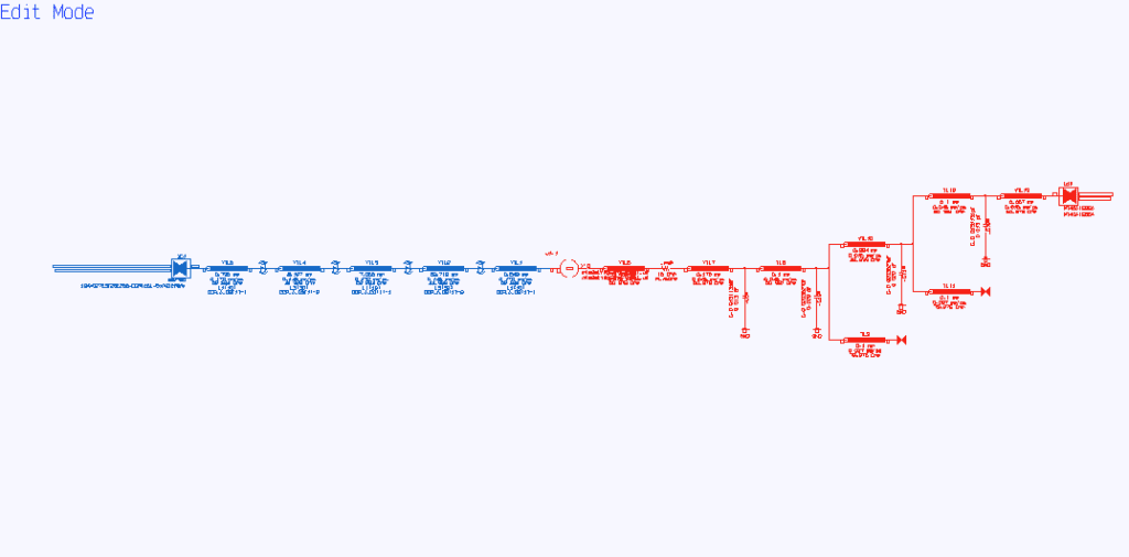
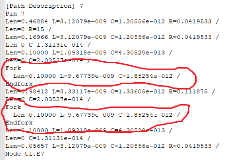
- The graphical connection can verify the [Path Description] in the EBD. In this case, there are two unconnected stubs in the picture. We can verify them with the EBD model Pin 7 [Path Description].
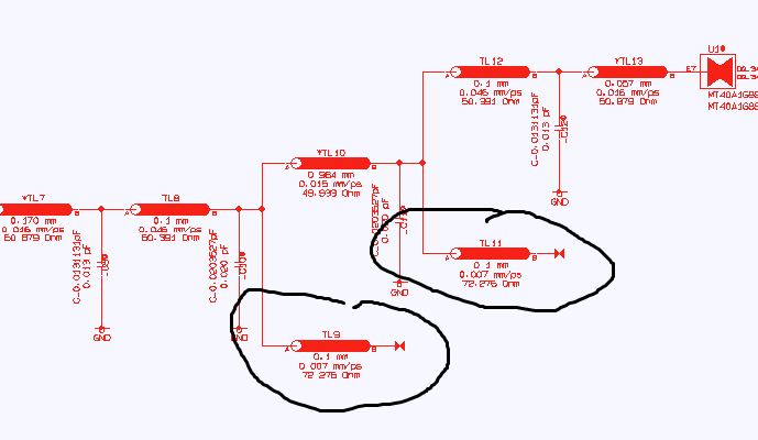
- The connections inside the EBD module are locked and cannot be changed, as the module design is fixed in the actual design process. The termination buffer (for U1.E7 in this case) can switch, as it is needed for different ODT settings.
Conclusion:
IBIS EBD brings tremendous value for high-speed designs using modules. However, due to its text format nature, it is not easy to verify syntax and identify potential errors. Therefore, the EDA tools you are using must have the capability to check the model syntactically using IBISCHK, then convert connections (Path Description) to a graphical display for visual checking in the topology editor.
Zuken’s CR-8000 provides all the essential functionalities for IBIS EBD model verification and simulation. It has an embedded IBIS Golden Parser for model syntax checking and displays the connections of [Path Description] in the Electrical Editor. These advanced features enable rapid and reliable design analysis for high-speed PCB designs with module boards.

- Blog
- Blog
- Blog

- Blog
Related Products and Resources

- Blog
- Blog

- Blog

- 2020 Technical Webinars
This webinar will explore a high-speed design process in CR-8000 that utilizes a constraint browser, topology template, crosstalk estimation, signal and power integrity simulations.