What’s New with E3.series Webinar Review
A new version of anything is exciting no matter how great the previous version. I realized it when looking for a new car and couldn’t wait for the new model year and test drive it. The webinar on What’s New with E3.series gave a lot of us with the same feeling of excitement – and a lot of questions.
If you are not up to date with the latest and greatest in E3.series 2017, I suggest the following 3-part blog series discussing the top 10 features and the What’s New webinar recording.
E3.series 2017 Top 10, Part 1
What’s New in E3.series Webinar
The webinar focused on the three main areas of improvement in E3.series 2017 and discussed functionality related to each area. It would be fair to say some of the improvements fall under multiple categories helping you save time, improve quality and are simple to set-up and use. The questions raised by the attendees were great as usual and answered during the webinar and in the Q&A section.

What’s New Features
The features discussed in each category are the most impactful ones; an exhaustive list can be found in the release notes for 2017.
Ease of use
- Intelligent bulk component insertion
- Align objects
- Cable ducts at any angle
- Optimize DXF graphics
Time savings
- ATA standard wire numbering
- Automated wiring enhancements – no more drawings wires!?
- Auto solve, sort and merge terminal strips automatically
Quality Improvements
- Select wire seals automatically
- Multiple pin terminals on pins
- Embedded documents in PDF
Zuken Community
We also discussed the Zuken community* where all the users can come together to share their experiences, solutions and suggestions. The community also has Zuken support experts to help with any questions the users come across. The community is replete with resources including ‘How to’ videos and articles for you to explore.
*Community access is limited to customers in the US and Canada at this time.
E3.toolBox
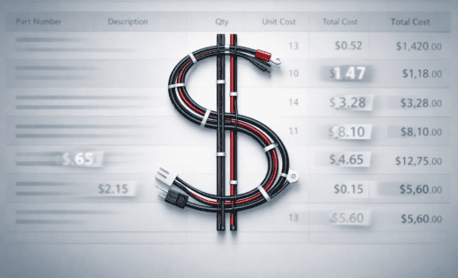
We introduced a new product called E3.toolbox to help create customized bills of materials, wire lists and to help document splices more efficiently. The E3.toolbox also enables the users to export bills of materials and wire lists to Excel with customized columns; the columns provide access to all the attributes in the library with a simple drop-down selection option.

Q&A
It is always interesting to see the questions and problems from users with varied design backgrounds and industries. Here is a summary of the some of the more interesting ones that came up during the webinar:
What is the default insert location in the device tree when inserting multiple components?
Response: The default location is the ‘Device Letter Code’ of the component in the device tree. The ‘Terminal Blocks’ come in as one strip to make it easy to manage a terminal strip.
Can you rotate a connector (terminals) without disconnecting wires – are the wire identifiers preserved after the connector is rotated?
Response: Yes, the connects can be rotated and the wires will reconnect if the Auto-Routing setting for ‘Reconnect after moving’ is turned on. The wire information is maintained automatically and only the connection is rerouted to maintain connectivity.
Can it auto place a cavity plug if no terminal is selected?
Response: A cavity plug can be selected as a default option when no wires are connected. The automatic selection of the cavity plugs works on the same principle as the automatic terminal and wire seal. The sealing parts are categorized as ‘Cavity Parts’ and are set-up in the library.
Is the custom BOM and Wire List option standard functionality with E3.series cable or is it a licensed feature?
Response: A new add-on E3.toolbox is a licensed product and is not a part of the E3.cable license. The ability to easily customize on-sheet and excel BOM/wire-lists based on customizable attribute selection can save a lot of time and increase productivity.
How to add fields to be included in the BOM or wire list that are not default in the E3.toolboox?
Response: The E3.toolbox provides any user with the ability to select or edit the symbol used for on-sheet reports. New fields can be added by adding a new column in the symbol and inserting the desired attribute text. E3.toolbox will fetch the contents of the attribute based on the columns added to the report symbol. The ability to customize the contents of the BOM and the wire list is the cornerstone of this amazing addition to your E3.series design package.
How does E3.series handle output to machining centers for drill/milling of panels and enclosures?
Response: There are multiple tools available to create DXFs or other documentation for your panel machining requirements – manually or automatically. The CutOut tool creates a DXF file from your panel design and can be found in the ‘TOOLS’ folder as part of your install files.
Additionally, interface tools for CNC/dedicated panel fabrication machines can be found as licenses or an output can be easily created using the scripting interface.
Are wire seals updated automatically if the library is updated/modified?
Response: Wire seals can be updated automatically based on the changes in the library for any given project by using the standard ‘Update in Project option’. The update in project settings in the project settings helps you manage the update process. Wire seals are to be considered as special attributes of a connector pin for customization requirement.
If you have a very large number of splices or shield terminators near a connector, is there a way to group them into a single symbol on the formboard so it can be a more abstract representation of many splices instead of many individual symbols?
Response: The answer is both Yes and No; the outcome depends on requirements of the splice part and the project settings. There is no default symbol to represent multiple splices, mainly due to the fact that a part number and a splice work with different wires and circuits. If you create a splice with multiple splices inside then it is possible to create a symbol to represent all the splices at a higher level and document the individual splices separately. This can be achieved by creating an assembly part out of the splices as well.
What is the difference between ‘wire length’ and ‘physical length’? I noticed that physical length is shorter after updating wire tables on a drawing.
Response: A wire is an intelligent and active part of your electrical design in E3.series. The physical length of the wire described the length on the formboard drawing based on the scale of the drawing. The wire length is usually longer than physical length since it is considering the real-world measurements of the wire in the form of strip lengths for the connector pin terminals, the connector size etc.
The response to the webinar was very positive and we are looking forward to sharing more information with the user community. We want to hear from you about the challenges you face and the solutions you need to improve your design experience. We encourage all of you to reach out to us in the community or through the blog to help us understand the topics that are most relevant to you.

-
Technical Marketing Manager

- Blog
- Blog
- Blog

- Blog
Related Products and Resources
- Products
The main goal of the Toolbox is to help you maximize production value by helping you create precise documentation without having to spend time customizing to meet different use cases.

- Products
- Products
- Products
E3.series is a Windows-based, scalable, easy-to-learn system for the design of wiring and control systems, hydraulics and pneumatics. The out-of-the-box solution includes schematic (for circuit and fluid diagrams), cable (for advanced electrical and fluid design), panel (for cabinet and panel layout), and formboard (for 1:1 wiring harness manufacturing drawings). Integrated with MCAD, E3.series is a complete design engineering solution from concept through physical realization and manufacturing output.