
Configurable Harness Design for Customizable Product Lines
Custom product configurations can create a documentation problem quickly. A single new radio, sensor, or subsystem can affect wiring diagrams, harness layouts, bills of materials, wire lists, and production instructions. For teams building aircraft, specialty vehicles, defense systems, or other complex products, those changes must be controlled without disrupting proven production workflows.
Product designs constantly evolve to meet customer needs. In the past, the lessons learned, design changes, and painful workarounds were passed from engineer to engineer and product line to product line. Today, digitally connected tools extend, modify, and maintain configurable harness design data over time with less manual rework.
Configurable harness design gives engineering teams a practical way to manage product line variants. It keeps the common base design intact while supporting the wiring changes required for customer-specific configurations.
Why product variants complicate harness design
Companies continuously innovate their product lines to meet customer needs. New features and subsystems require updated wire harnesses that connect back to the existing system design.
High-volume product lines, such as cars, produce thousands of units from a curated list of possible features. This approach supports standardized harnesses and repeatable production processes.
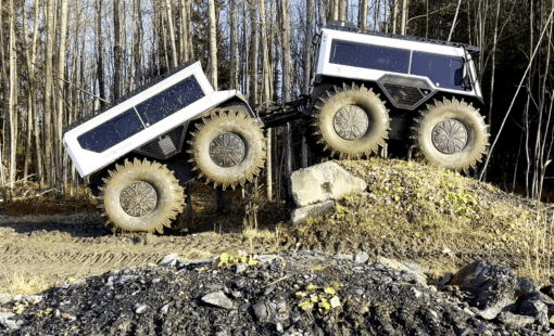
Lower volume products, such as aircraft or specialty vehicles, are different. Each build may introduce a unique feature set. These configurations often start from a base system, with wiring variations made at the factory, in the field, or at a modification center after production.
Each approach requires different engineering documentation and work instructions. When the inevitable top-level change orders arrive, a common base design helps reduce the ripple effect across variants.
How modification kits support configurable harness design
In a perfect world, engineering teams would never repeat work. However, there are cases where doing work twice makes good business sense when it protects a mature production line.
Imagine a well-optimized production line building large quantities of a standard product. Then a customer requests a small quantity with slight differences. Engineering and manufacturing teams typically have three options.
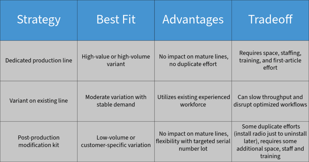
The third approach listed above is the modification kit strategy. In this workflow, the base product is produced on the optimized line. Then the required changes are applied after production.
Industries such as aerospace, specialty vehicles, and military systems commonly use modification kits to reuse core engineering work while still meeting unique customer requirements. This approach helps teams support configurable harness design without rebuilding every variant from scratch.
Why modification kits need connected documentation
Post‑production modification requires a dedicated and distinct set of engineering documentation. The drawings intentionally differ from standard production drawings.
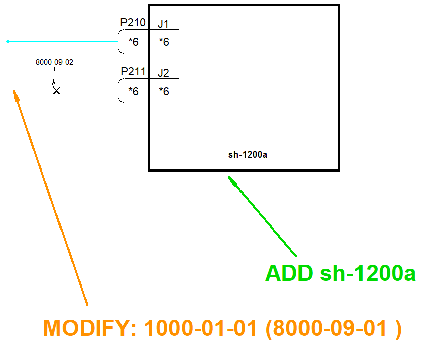
Modification drawings often share many core elements with production drawings. This can include wiring diagrams, layouts, bills of materials (BOMs), and wire lists. However, they also need clear ADD, REMOVE, and MODIFY callouts that define how the base configuration changes.
This documentation must remain tightly coupled with the production drawing lifecycle. Changes to the production configuration often require corresponding updates to the modification drawings. As variants increase, maintaining consistency becomes complex and error-prone.
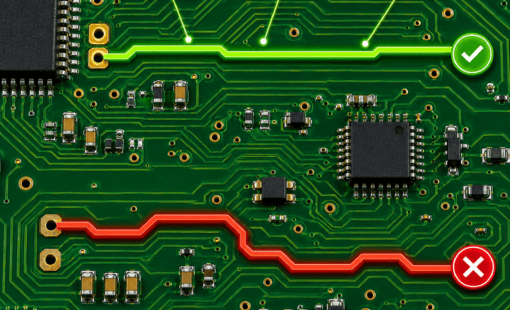
This is where disconnected tools create risk. A change made in one drawing may not appear in another. A BOM may no longer match the modification instructions. A technician may receive documentation that looks correct but no longer reflects the latest design intent.
Managing base, production, and modification drawings in E3.series
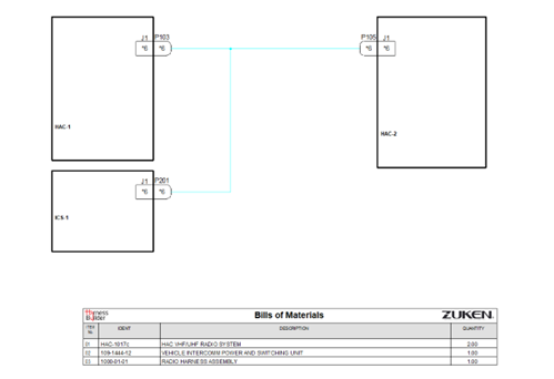
The foundation of a configurable design is the base system and its supporting cable harnesses. In the example, the baseline system (2000-01-01) includes two radios (HAC‑1 and HAC‑2) connected to an intercom system (ICS‑1). This system-level base design drawing captures the product line’s core configuration.
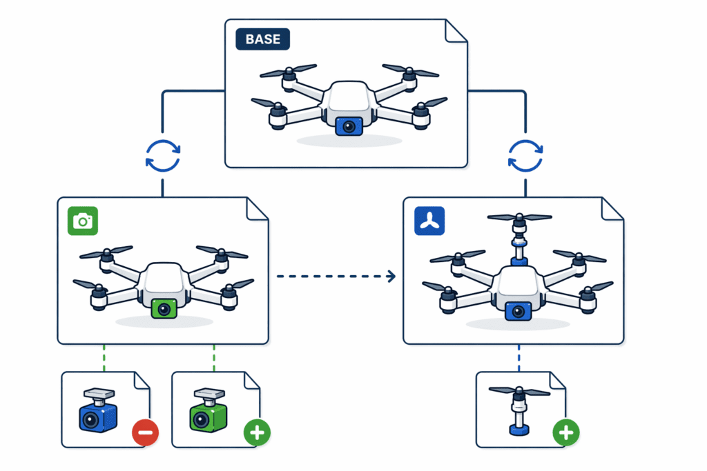
When a new customer requests an added radio, two drawing sets are needed:
- Production drawings that show the final build configuration.
- Modification drawings that show the differences between the base design and the new configuration.
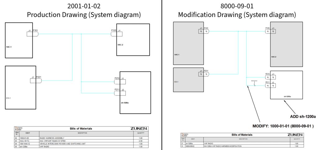
The production drawing is straightforward to build from. It shows the complete configuration for manufacturing. In contrast, the modification drawing is built for work away from the main production line. It uses action arrows, change callouts, and a changes-only BOM to show what must be added, removed, or modified.
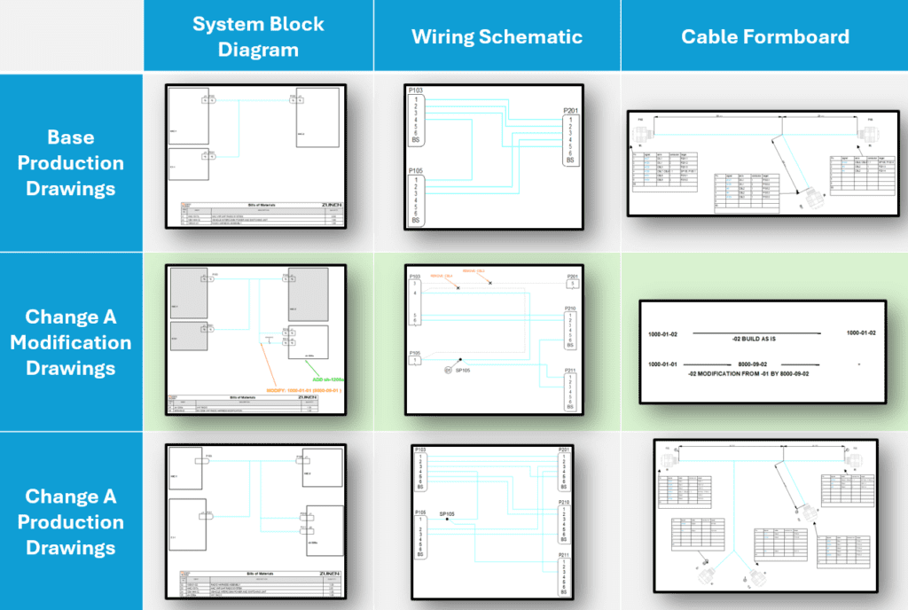
A simple radio addition can require multiple outputs, including system diagrams, schematics, formboards, BOMs, and wire lists. Multiply that across several product variants, and the documentation workload grows quickly.
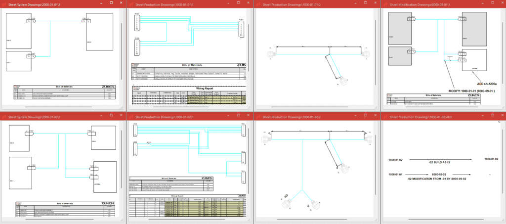
E3.series helps teams manage this complexity by keeping devices, drawings, BOMs, and wire data connected. Instead of manually reconciling each drawing set, engineers can work from linked design data that supports both production and modification outputs.
How E3.series reduces rework across harness variants
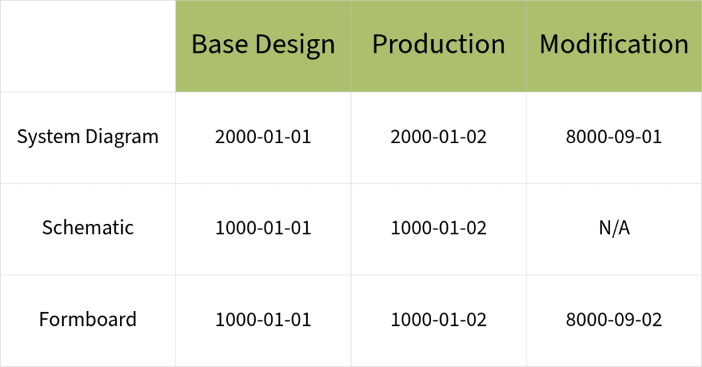
E3.series supports configurable harness design by synchronizing data across drawings. For example, a structured range of view numbers can help ensure changes to the base design propagate to related production and modification drawings.
This connected approach also supports Harness Builder reporting. Even when the same device appears on multiple drawings, engineers can generate reports within the appropriate scope, such as a sheet, assembly, or structure node.
Changes to the base design are inevitable. Fortunately, E3.series maintains logical links between devices and documentation. This reduces the scope of design rework and lowers the risk of production impact.
E3.series also supports intelligent modification callouts. Engineers can create ADD, REMOVE, and MODIFY symbols that combine fixed text with live design attributes, such as component code or assembly device name. When the underlying data changes, the callout updates with it.
This helps teams communicate changes clearly while keeping documentation aligned with the design. It also reduces the manual checking often required when managing many product variants.
Managing complex product variation with connected design tools
Configurable harness design is ultimately about balancing flexibility with control. Customers want product options. Engineering teams need to deliver those options without destabilizing mature production systems. A well-structured base design makes that possible. Modification kits give teams a practical way to support low-volume or customer-specific changes. Connected design tools help keep production drawings, modification drawings, BOMs, wire lists, and callouts aligned as designs evolve.
With E3.series, engineers can support custom configurations, post-production modifications, and ongoing change orders with less rework and better traceability. Whether the change is a part number update or a more complex wiring modification, the underlying design intent remains connected.
Learn how Zuken helps engineering teams manage product line variants without disrupting production

-
Applications Engineer

- Blog
- Blog

- Blog

- Blog
Related Products and Resources
- Blog

- Blog