5 Things to Think About When Designing Power Control Panels
What are the 5 key things to consider when designing control panels?
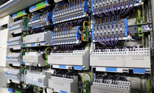
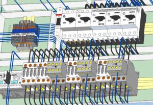
The design of power control panels, like the one shown below, is no simple undertaking. There are several key aspects to carefully think through when designing these panels. Let’s take a look at five key considerations when designing power control panels.
#1: Think about Wire Routing from the Beginning
Wire routing is essential when making a power control panel that involves more than a 2D layout schematic. Designers must carefully consider many interacting factors, such as the size of the wire, the fill of the wiring ducts, and how to uphold logical connectivity while calculating routes.
First, choose the correct wire size. A change in size can be difficult to implement once the design is in process unless special tools are available to reflect those changes through the 2D schematic and the 3D cabinet, wiring ducts, logical connections, and routing.
Furthermore, engineers must ensure that they do not exceed duct fill capacity. Ideally, they should work to optimize the duct fill to save precious space in the design (and help reduce costs by eliminating unnecessary ducts). Highly accurate wire length calculations are essential to facilitate easy installation of panels later on. In short, there is much more to wire routing panels–like the one shown below–than simply keeping track of logical connections.
The ability to route and calculate wire length automatically, even when moving parts or components during design, makes the routing process much more manageable. Moreover, precisely calculated wire lengths (with checked wire cross-sections) enable the ability to label and assemble wires in advance. This, in turn, significantly reduces assembly time and errors. Specialized software makes this possible, as we will see shortly.
#2: Be Ready to Deal with Part Collisions
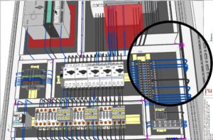
Because wiring schematic diagrams are traditionally 2D and the implementation of actual wiring is in a 3D world, part collisions and clearances can quickly become a severe problem. Even when working carefully between 2D and 3D views, collisions can still be challenging to detect and fix. The sooner engineers recognize collisions, the sooner the entire design process can progress.

Conceptually viewing the 3D envelope of the components will make collision detection easier, especially when moving and placing elements in the cabinet during the design phase. Avoid many common part collisions through keep-out and height restrictions on the control panel design.
#3: Build in Clearances Early and Often
Engineers may also want to incorporate clearances into their designs. For example, UL (Underwriters Laboratory) clearances recommend that designers ensure adequate room for ventilation when including heat-producing devices in a design. In addition, to ensure adequate space for installers to make power connections, the NEC requires a specific bending radius for incoming and outgoing power connections.
One solution to this problem is a design platform that supports automatic collision and clearance checks during the active placement of components, like Zuken’s E3.series. Read on for more information about this solution!
#4: Synchronize 2D and 3D Work
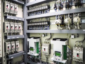
The physical layout of a cabinet must correspond to the logical connectivity represented in its electrical schematics. If a designer doesn’t account for this from the beginning of the process, it can be difficult to ensure consistency. When adding a new part to the control panel layout, the related schematics and views must also reflect this change. This can be challenging to stay on top of, even with relatively simple designs like those shown below.
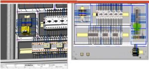
Most engineers generating the schematic and logical connections are masters in the 2D environment, but learning the ins and outs of complex 3D design systems can be overwhelming. One clear solution to this problem is to find a development environment that supports design in 2D and quickly translates to 3D with automated updates between the two.
#5: Embrace Digital Manufacturing
It is no overstatement to say that making a power control panel is an intricate process: designers will use cutting, punching, and drilling tools involved in the panel itself, not to mention details related to the wiring needed (and the navigation of wire lists that include length and route information). Even the wire preparation machinery requires particular data to ensure correct installation in all aspects of the panel.
Digital manufacturing offers new, simplified ways to deal with these logistical problems and much more. Digital manufacturing enables designers to extract mounting and cut-out information for use by automated CNC drilling and milling machines. It also enables teams to acquire accurate wire lengths and termination information for use by automated wire-cutting and processing machines, as well as providing data to support interfacing with wire labeling systems.
E3.panel: The Zuken Solution for Designing Power Control Panel
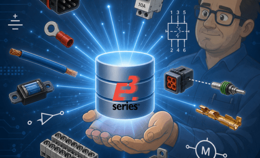
As part of the Zuken E3.series tool suite, Zuken offers E3.panel for cabinet design: an innovative, powerful addition to the E3.series ecosystem that supports users in the design, manufacture, and assembly of power control panels.
For wire routing, E3.panel can optimize duct filling, select the right wire size, account for current chains, and accurately calculate wire lengths. To avoid part collisions, E3.panel can generate a full digital mockup to assess spacing, detect clashing, and implement keep-out and height restrictions. It also provides live feedback during design to troubleshoot and prevent common issues, such as ensuring proper implementation of clearances.
When it comes to synchronizing 2D and 3D, E3.panel allows engineers to begin working either in the panel or on the schematic and–even more importantly–automatically reflects any changes across both. Its 3D interface does not require users to learn the time-consuming details of working in 3D. Engineers can easily validate the form, fit, and function of cabinets by implementing design rules.
Digital manufacturing is also fully supported by Zuken E3.panel through the ability to complete the following tasks:
- Export highly accurate 3D data from STEP models
- Generate detailed mounting descriptions
- Export data for automatic wire labeling, cable duct and mounting rail cutting, wire cutting, and wire processing
In addition, E3.panel has interfaces available for connecting data to wire-cutting and processing machines such as Argus, Komax, and Schleuniger.
Conclusion
Designing a power control panel includes details such as wiring routing, part collisions, clearances, synchronizing 2D and 3D digital models, and digital manufacturing. Zuken’s E3.panel can help you with these design aspects and much more. Contact Zuken today to learn how our tools can speed up the design, manufacturing, and assembly of your power control panels.

-
E3.series Technical Marketing Manager


- Blog
- Blog
- Blog
- Blog