
Top E3.series 2026 Features for Smarter MCAD Electrical Integration
Harness projects move fast. Space is tight, options multiply, and changes never stop. MCAD electrical integration in E3.series 2026 helps electrical and mechanical teams stay in sync without extra clicks or manual cleanup. The 2026 release strengthens data exchange, improves flattening accuracy, and speeds the ECAD–MCAD round‑trip.
If you manage complex assemblies, you need reliable context flowing both ways. Missed attributes cause rework. Inaccurate formboards drive fit issues. The updates below aim at those pain points.
The MCAD Electrical Integration Workflow, Refreshed for 2026
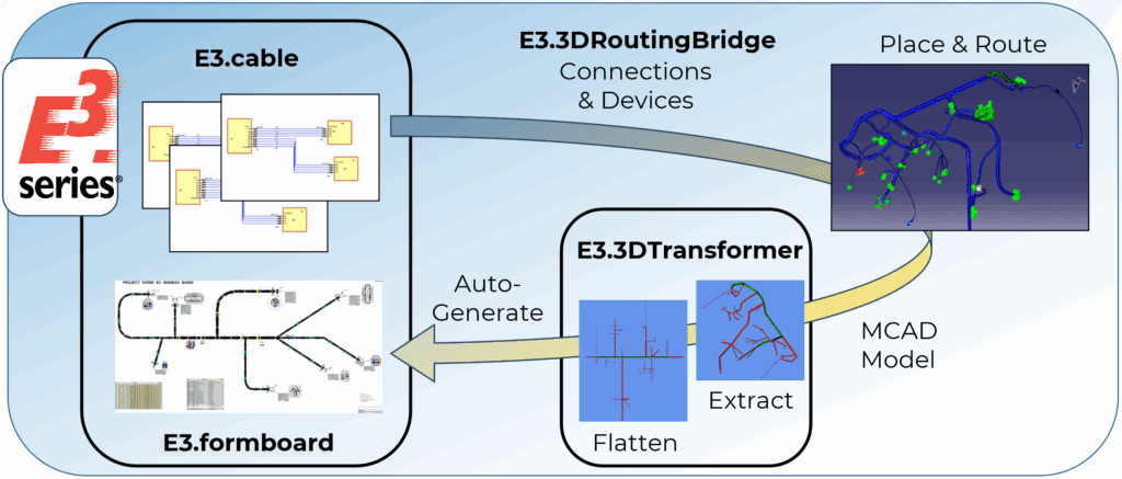
E3.series connects schematic design, 3D routing, and manufacturing outputs in a clear loop. Typical flow: ECAD creates the harness, the team routes in MCAD, then the harness is flattened and documented in E3.formboard. The 2026 enhancements reduce translation effort at each handoff and improve MCAD electrical integration fidelity.
More Electrical Context Flows into Mechanical
Mating Part Information
Connector placement improves when MCAD sees the full picture. E3.3DRoutingBridge now exports mating part information along with the connector. Designers position the pair correctly the first time. Clash checks become more reliable. Assembly teams avoid late rebuilds.
Parent Assembly Attributes
Traceability matters. The export can include parent assembly attributes such as harness part numbers or system IDs. MCAD users can search and filter by these values. PDM systems capture the right links. Teams keep a clean thread from requirements to installation.
Smarter Flattening for Accurate Manufacturing
E3.3DTransformer flattens 3D models into 2D formboards for manufacturing. Traditional flattening algorithms oversimplify geometry, causing builds to deviate from the original design intent. As harnesses grow more complex and space constraints tighten, accurate 2D flattening becomes essential. Here are two key enhancements to Zuken’s flattening methodology.
Maintain T and Y Branch Angles
Traditional flattening algorithms convert angled Y branches into right-angled T branches. That shift looks small on screen but causes fit problems on the vehicle or machine E3.3DTransformer 2026 preserves T and Y branch angles from the 3D route. The 2D formboard now mirrors true geometry. Technicians recognize the shape and pull harnesses faster.
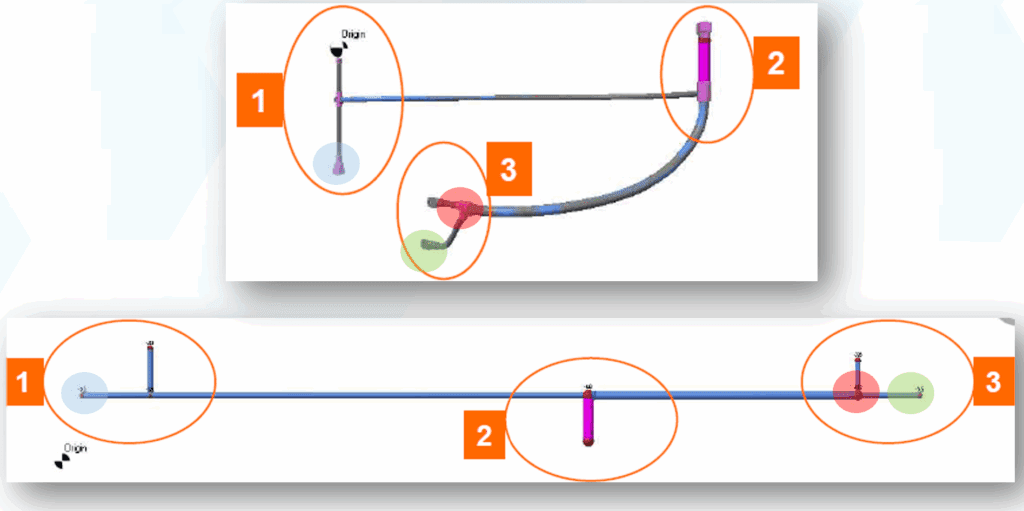
This new feature keeps the 3D model branch angles, ensuring the 2D representation accurately reflects real-world geometry. For harnesses in tight installation spaces or with thick wire bundles, small deviations in angle can lead to fit issues or increased strain. Maintaining these angles reduces costly rework and improves design fidelity.
Set From/To on Backbone from Left to Right
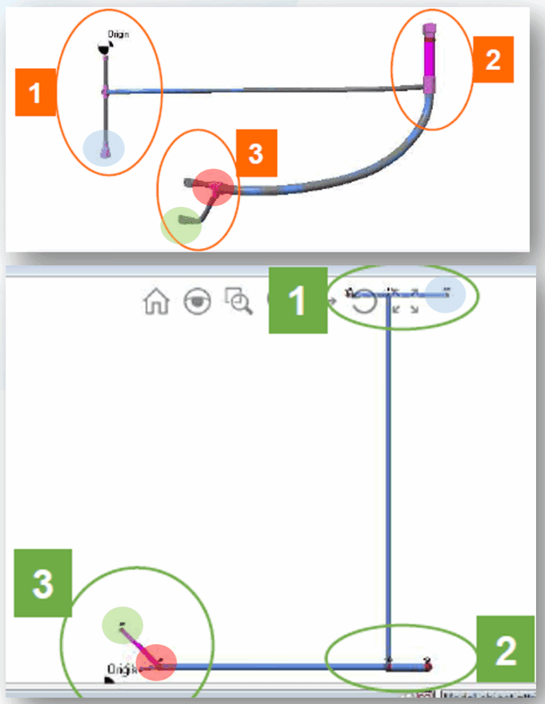
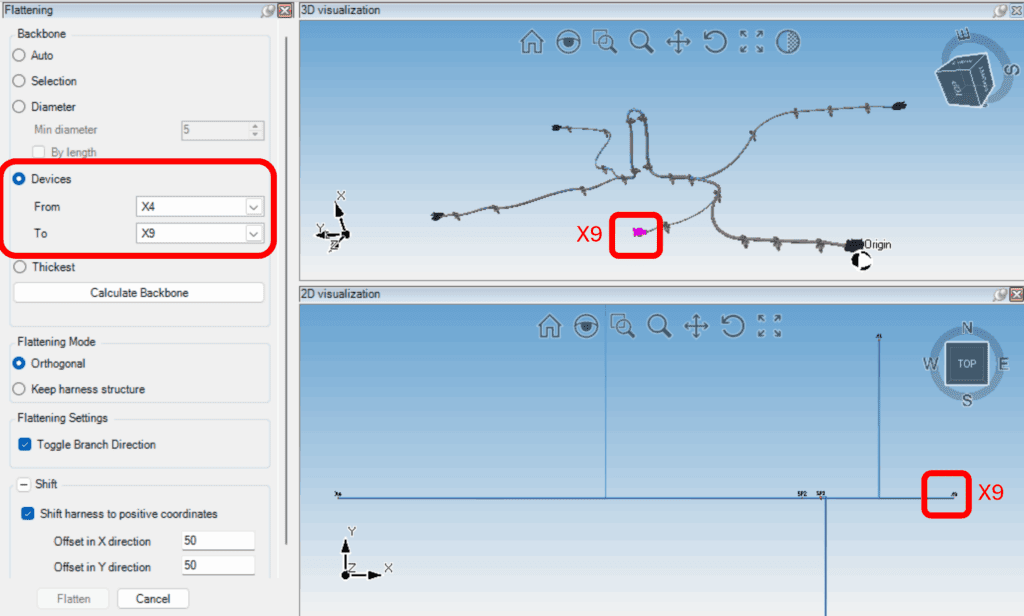
Engineers create 2D formboard layouts to provide an intuitive visual guide for manufacturing. Formboards read best when the backbone flows left to right. This new feature allows engineers more control to define the flattening backbone manually. The system now places the “from” on the left and the “to” on the right.
This granular control helps create formboards that reflect the original harness. Clearer formboards reduce interpretation errors and accelerate technician training.
Streamlined MCAD-to-E3 Workflow
The E3.series 2026 MCAD electrical integration enhancements streamline the data exchange from the mechanical tools to the electrical team. Our team focused on making E3.3DTransformer easier to use while expanding the amount of information transferred.
Batch Start
Many teams launch flattening from their PDM system. In 2026 users can now launch the E3.3DTransformer tool via a batch script. Select the relevant assembly and trigger E3.3DTransformer directly from the PDM environment.
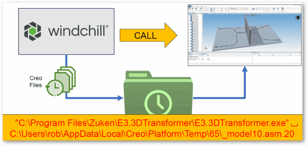
This update streamlines workflows by reducing the manual steps needed to start flattening the 3D model. This repeatable process saves time and ensures consistency when working across multiple assemblies or projects.
Separate HLA and Location Attributes
Previously, the tool required concatenating the connector’s name, higher level assignment (HLA), and location into a single field. This workaround addressed limitations in MCAD tools that didn’t support separate fields for HLA and location. With this new feature, these three elements can now be mapped individually. This aligns naming conventions between MCAD tools and E3.series for better traceability and understanding between disciplines.
Additional Parts as Attribute
Harness design often specifies installing connectors with additional components like housings, seals, or backshells. Accessories and clips often fall through the cracks. With this new feature, engineers can identify parts in the 3D model and assign these additional parts as a connector’s attribute in E3.series.
This helps BOM management by ensuring E3.series captures connector accessories properly. Manufacturing benefits because the tool groups relevant parts together instead of loading them as independent items. Together, these updates represent a significant step forward in cross-domain collaboration.
Results You’ll See
Engineering changes still happen, but they land softer. MCAD receives more context, so placement is right on the first pass. Flattening keeps real angles, so the formboard reflects reality. PDM launches run in a repeatable way, so builds move without stalls. The net effect is fewer re‑routes, fewer line‑side surprises, and a schedule that holds.
Quick scenario: A commercial vehicle team routes a cabin harness in MCAD. Mating parts guide connector placement. The backbone runs left to right on the 2D board. Additional clips appear on the BOM. Production pulls the board and finishes the subassembly a day earlier than usual.
How this Supports Emerging Trends
Vehicle platforms pack more options into the same space. Aerospace and machinery programs face similar constraints. Wiring must fit the first time, and every part needs a digital thread. E3.series 2026 aligns with that reality by carrying richer attributes, enforcing consistent orientation, and automating handoffs. These are practical steps toward a dependable electrical digital twin.
Summary: MCAD Electrical Integration in E3.series 2026
MCAD electrical integration in E3.series 2026 helps electrical and mechanical teams move faster with fewer errors. Engineers can export richer context, including mating parts and parent assembly attributes, so placement is right the first time. Smarter flattening preserves true T/Y branch angles and lets you set backbone direction for consistent, technician-friendly formboards. Batch launches from PDM and cleaner field mappings speed the ECAD–MCAD round-trip and keep BOMs accurate. The result: better traceability, less rework, and schedules that hold—practical steps toward a dependable electrical digital twin.
Get Hands‑on
Ready to explore the updates?
- Register for What’s New in E3.series 2026 for Wire Harness Design webinar.
- Visit the E3.series MCAD Integrations page to see supported CAD tools and workflows.
- Watch a webinar discussing the efficiencies of an MCAD 3D flattening flow.
- Review E3.formboard features for documentation and manufacturing.
- Prefer to talk through your use case? Contact our team to discuss MCAD ECAD integration software options.

-
Application Engineer

- Blog

- Blog

- Blog
- Blog
Related Products and Resources
- Blog

- Blog

- Webinar