
Designing Pneumatic Schematics in E3.series
Pneumatic systems are everywhere, playing a vital role in industries where fast, precise, and reliable actuation is required. They power robotic arms in industrial automation, regulate gases in semiconductor manufacturing, and operate valves in nuclear power plants. Pneumatic actuation converts compressed air into motion and is often a faster, safer, and cleaner alternative to electrically or hydraulically driven systems. Pneumatic schematics are essential to support the design, build, and long-term maintenance of these systems. As engineering teams face increasing pressure to deliver quickly and accurately, having a streamlined pneumatic design process is essential to staying competitive.
Basics of Pneumatic Design
Pneumatic design begins with identifying the system’s motion requirements and selecting actuators and control valves that meet those needs. Actuators can be linear or rotary, and they vary in force delivered and control method. Typically, the system requirements drive the actuator selection.
Control methods are defined next. A control input can be manual, like a push button, or driven by sensors that measure flow, temperature, pressure, or other details about the system. In modern systems, these inputs are fed through a programmable logic controller (PLC), which sends signals to drive the actuators.
Air preparation is another critical element when designing pneumatics. Filters, regulators, and lubricators ensure a clean and consistent air supply. These components must be selected based on system requirements like air quality, flow rate, and environmental conditions.
Tubing, fittings, and accessories tie the pneumatic system together. These elements must be sized and specified to support flow and pressure needs while considering installation constraints and serviceability. Every detail contributes to system performance, safety, and reliability and is documented in the pneumatic schematic.
Pneumatic design is also highly collaborative. Mechanical engineers define the physical space requirements. Software engineers program the PLC. Manufacturing teams offer practical feedback to build the system effectively. Success depends on coordinating across disciplines and having a shared understanding of the design.
Why Pneumatic and Electrical Design Goes Hand in Hand
At first glance, engineers may consider pneumatic systems part of mechanical design because they push air through components to drive actuators. However, electrical subsystems often control their operation. These include PLCs, electrically controlled valves, and sensors. In most cases, a pneumatic system is part of a larger electromechanical design.
Developing electrical and pneumatic schematics separately increases the risk of mismatches, duplication, and communication errors. Engineers may often overlook changes in the electrical control system that are not reflected in the pneumatic diagram, and vice versa.

Designing both systems in a shared environment helps eliminate these risks. Engineers can streamline development, maintain synchronized component references, and easily coordinate signal control with mechanical actuation. Cross-discipline visibility reduces manual coordination and potential for error, shortens development time, and ensures better system reliability.
Pneumatic Design with E3.series
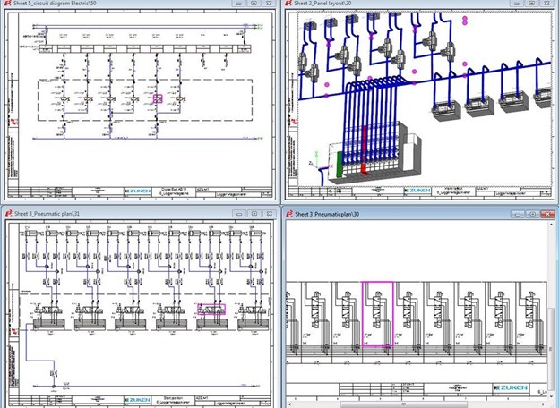
Zuken’s E3.series software suite provides a comprehensive solution for multi-disciplinary system design, including robust support for pneumatics. Its integrated platform enables engineers to create pneumatic schematics using ISO-compliant symbols and manage tubing, valves, and sensors in a database-driven environment.
Built-in symbol libraries, part selection features, and design rule checks help streamline the process and reduce common design errors and development time. For example, the software validates tubing sizes to ensure the system consistently meets pressure and flow requirements.
A key advantage of E3.series is the ability to design electrical and pneumatic schematics within the same project environment. This unified approach allows both disciplines to remain synchronized during development. The shared parts library stores electrical and pneumatic attributes for each component, assisting engineers in both disciplines in selecting the proper part. Additionally, when one discipline changes a designator or part, the system automatically updates it in the other. This cross-functional consistency improves documentation accuracy and supports a smoother transition from design to manufacturing.
With E3.series, engineers can create process gas delivery diagrams, piping and instrumentation diagrams, and I/O assignments, as well as build documentation, all within the same project environment.
Full System Integration and Lifecycle Support
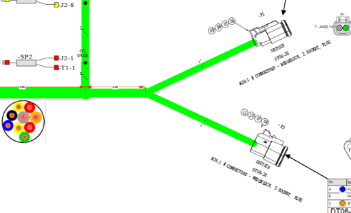
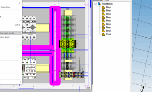
Pneumatic schematics are only one part of the larger engineering workflow. E3.series supports integration with mechanical CAD systems needed for routing pneumatic hoses and electrical cables. Engineers can export device data into MCAD to drive routing and import length data into E3.series to define the bill of materials.
E3.series also integrates with leading PLM systems. This integration allows for consistent version control, change tracking, and secure access to design data throughout the product lifecycle. The result is a more connected, efficient, and traceable design process.
Designing pneumatic schematics requires precision, coordination, and speed. By bringing electrical and pneumatic design into one cohesive environment, E3.series empowers engineers to work more efficiently, reduce errors, and deliver higher-quality automation systems.
Contact Zuken today to schedule a demo and learn how E3.series can support your team’s pneumatic design needs.

-
Application Engineer

- Blog

- Blog
- Blog

- Blog