Comprehensive Systems Design Language (CSDL) vs. SysML? You Can Have Both
Why language—and CSDL—matter in MBSE
Miscommunication sinks projects. Even when requirements are “correct,” teams can still misinterpret intent. The Comprehensive Systems Design Language (CSDL) addresses this by expressing systems concepts as clean, human‑readable statements while keeping the semantic precision engineers need. That combination helps systems engineers act as effective translators for business, design, and test stakeholders.
What is the Comprehensive Systems Design Language (CSDL)?
CSDL is a systems modeling language based on natural language parts of speech. Classes map to nouns, relationships to verbs, and attributes to adjectives. You can read the model as simple, precise sentences: A component performs a function. An Engine performs Propel Vehicle. These statements are unambiguous and fully traceable in the model.
CSDL covers the core of systems engineering and more:
- Requirements (needs, constraints, rationale)
- Functional architecture and behavior (functions, flows, scenarios)
- Structural architecture (components, interfaces)
- Verification and validation (methods, test cases, results)
- Program Management (work breakdown structures, organizational structures, program activities, decisions)
- Specialty Engineering (such as FMEA)
Because constructs are formally defined, tools can enforce completeness and consistency and support analysis and simulation.
CSDL and SysML: better together in GENESYS
Choosing CSDL does not mean giving up SysML. In GENESYS, you model in CSDL and still produce the full suite of SysML V1 diagrams automatically and consistently. That means you can show stakeholders more easily understood views like hierarchy or physical block diagrams (PBD), while systems engineers can simultaneously access detailed BDD/IBD, activity, and other SysML views from the same data.
Teams also benefit from a shorter learning curve. Stakeholders who rarely use SysML can still consume the model through natural‑language views, while specialists keep the rigor and depth they expect.
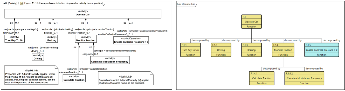
The SysML activity diagram on the left offers greater detail through specialized notation, but its complexity can be a barrier for stakeholders unfamiliar with SysML. In contrast, the hierarchy diagram on the right presents a simplified view that is easily understood by a broader audience. GENESYS supports both representations, allowing users to tailor the view to the needs of specific stakeholders.
Example: Leadless pacemaker—clear communication across stakeholders
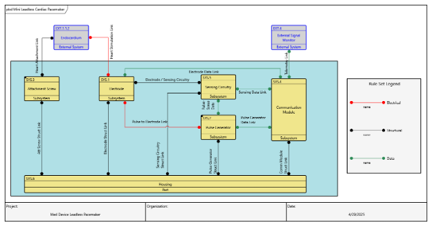
Consider a leadless pacemaker. Start with captured needs and derived requirements. Next, express the context: the device interacts with the surgeon, catheter for insertion, an external signal monitor, and the patient. A PBD highlights the actors and links in natural language for broad audiences, while an IBD adds ports, item flows, and signals for designers.
For structure, a BDD decomposes the pacemaker into lower-level parts such as electrode, pulse generator, attachment screw, communication module, sensing circuitry, and housing. The corresponding hierarchy diagram reads as sentences for clarity. Inside the device, a PBD depicts internal electrical, structural and data links in a format that looks much more like a schematic; engineers can open the synchronized IBD for port and signal‑level detail. Finally, use cases describe intended operation, with property sheet attributes providing additional detail that facilitate easily generated textual documentation straight from the model.
Tailor and extend: compliance and analysis
Many programs need domain‑specific concepts. CSDL supports extensibility so that the language can be expanded and enhanced with new features, components or capabilities without disrupting the existing functionality. Two practical examples:
- ISO 14971 (medical device risk): extend Use Case with an attribute to distinguish intended use vs. reasonably foreseeable misuse, and style them differently on diagrams. Now reviewers can validate coverage at a glance and use the model to generate compliance reports.
- FMEA: add classes like Failure Mode, Detection Method, Effect, and tie them to existing components, functions, and requirements. Diagrams such as spider or hierarchy views then read as clear sentences that trace causes to effects and mitigations.
Conclusion and next steps
CSDL gives you clarity without compromise: natural‑language communication, formal semantics, completeness checks, and interoperable SysML views generated from a single source of truth in GENESYS. As digital engineering practices mature and standards evolve, an extensible language helps you keep pace and keep stakeholders aligned.
- Watch the recorded webinar: Natural Language Meets Systems Engineering (CSDL)
- Explore MBSE with GENESYS and request a demo
- Read about the STRATA methodology to structure your models
- Download the MBSE Primer to get your team aligned
Related blog posts:
- How CSDL Enhances Model Traceability and Structure in GENESYS
- Advancing MBSE – Value of CSDL in a World Shaped by SysML
- Modeling Clarity – Applying CSDL to Real-World Systems Engineering, part 1
- Modeling Clarity – Applying CSDL to Real-World Systems Engineering, part 2
- The Power of Modeling Language Extensibility with CSDL

-
President & CEO of Zuken Vitech
Brian Selvy is President & CEO of Zuken Vitech. He has worked in the aerospace, optical observatory, and defense system domains, and has held senior systems engineering positions at the U.S. Extremely Large Telescope Program. He also worked at SpaceX in their early days, where he was responsible for the Falcon 1 ground support systems.

- Blog

- Blog

- Blog

- Blog
Related Products and Resources

- Webinar
- Blog
- Products
Digital Engineering requires a model-based design process that begins in Systems Engineering. Zuken acquired Vitech Corporation, a leader in Systems Engineering practices and MBSE solutions, with the intent of implementing an E/E model-based design process.