Is there a Model-based Engineering Process Problem? – Part 2
In part 1, we established that there is indeed a model-based engineering process problem. The problem is the gap between digital engineering and model-based engineering. In this post we’ll talk about solutions for connecting the model to detailed design.
Consider the time that went into building your high-fidelity product model consisting of architecture, requirements, functions, risks, etc. Now, consider how you will move all that information to the detailed design team. Not surprisingly, the most common approach is to convert the model to documents. On the surface, that seems like a reasonable approach. But, it disconnects the model from the design process and essentially puts it on an island. This approach significantly compromises the product model value.
Expose the Model to the Design Team
Zuken takes a different approach. In 2021, we released a connector that bridges the model to the wire harness design process–E3.GENESYS Connector. So instead of converting the model to documents, we expose model content and transfer the architecture to the detailed design process. First, the detail designer uses E3.GENESYS Connector to open a window into the model. This approach keeps the model relevant through the detailed design process. Next, from E3.series, Zuken’s wire harness design tool, the engineer can see requirements, parameters, and diagrams. This visibility provides the engineer with the “design envelope” required to design and build the harness.
When discussing a model-based engineering process, the term “expose” is an important one. We expose the model content to keep the model relevant and active in the design process. Therefore, any changes to the model are visible to the design teams. Here’s why that connection is essential. During architecture verification of any subsystem, the design team might determine they cannot meet a verification requirement. As an example, let’s say it is a weight requirement for the electronic control unit (ECU). First, this verification failure is reported back to the systems engineering team with a “cannot meet” status. Then, the conversation starts to reallocate more weight to the ECU or change the design envelope to reduce implementation weight. Finally, once systems engineering decides on the best path, the design team can open that window into the model and see the changes.
Transfer the Architecture
Earlier I mentioned exposing the model content to the design team. That is the first half of the solution. The second half is the ability to transfer the architecture, in this case, to the E3.series topology editor. The model must provide the architecture, not a detailed schematic, which is a common mistake. What’s the difference? In the illustration below, the Flight Controller PCB has six “links” or connections. This is the architecture representation. Based on requirements and experience, the detailed design team may decide to combine the six links into three connectors. That is because the model provides the systems engineer’s design envelope and not a schematic.
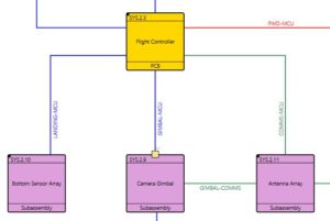
What goes into the product model will be the topic of a future post. For now, let’s just say the architecture is a block diagram that when combined with the requirements, provides the design team with the necessary information to build it. E3.GENESYS Connector can directly move that architecture diagram into topology and then display requirements and parameters for each selected block. This model interaction keeps the model relevant, which is the prime directive.
Design the PCB First
As we validated our approach to connecting the model to detailed design, we discovered that companies were designing the PCB first and then the harness. This is an important observation in a model-based engineering process. The model shows “links” or connections to the PCB. During PCB design, those links can be combined into one, two, or more connectors. The connector configuration (i.e., pin assignments) is the domain of the detailed designer, not the systems engineer. However, this statement requires a qualifier; there may be cases where the model specifies a connector and pin out. Assuming the PCB is designed first, Zuken provides an IPC-2581 connection between the PCB and wire harness design tools. This connection eliminates pin assignment errors by using standards and avoiding documents. Avoiding documents is an essential pillar of digital engineering.
Check Out the Webinar Series
Zuken, Vitech, Phoenix Integration, and Ansys EMA3D put together a four-part webinar series demonstrating critical design steps in a model-based engineering process. Using a video drone for the product build, the webinars step through model creation, model optimization with trade studies, transition to detailed design, and EMI analysis of the wire harness in the drone. Anyone interested in learning more about developing a model-based engineering design process for product development should check out these webinars.

-
Vice President of Marketing, Zuken USA, Inc.


- Blog

- Blog

- Blog
- Blog
Additional Products and Resources
- Blog
- Blog
- Blog
- Blog