CR-8000 Release 2023
Menu
Discover the latest updates in CR-8000
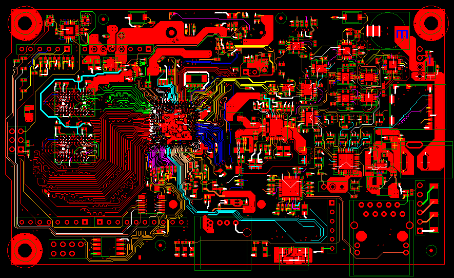
CR-8000 Release 2023 includes enhancements to support design efficiency and analysis, enabling users to tackle the challenges of high-density, high-speed PCB designs. A specific focus was given to reorganizing and extending CR-8000’s comprehensive range of signal integrity, power integrity, and EMC analysis tools, now packaged in the configurations of CR-8000 Design Force Analysis Advance.
The engineering frontend, CR-8000 Design Gateway , has been improved to facilitate design reuse and protect confidential information. Zuken’s industry-leading 3D multi-board design toolset, CR-8000 Design Force, has gained automated functionality in the areas of mesh plane and copper area generation, along with enhanced semi-automatic routing.
Load sheets from multiple designs to create a new design
CR-8000 Release 2023 offers enhanced creative capabilities, allowing you to effortlessly generate new designs by seamlessly loading sheets from multiple existing designs. This feature enables the incorporation of specific elements from various designs or the utilization of template designs as a solid foundation. With the flexibility at your fingertips, you can select and employ only the required sheets from arbitrary circuits, streamlining the design process and granting you the liberty to materialize your innovative ideas.
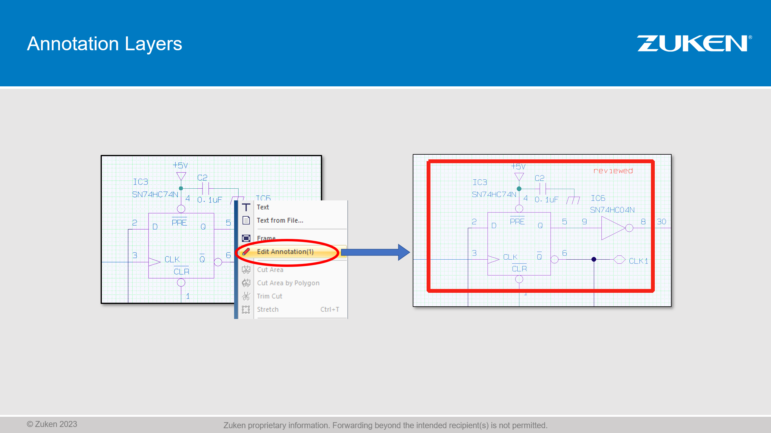
Create additional annotation layers
CR-8000 Release 2023 provides an enhanced schematic design experience by introducing the capabilities of additional annotation layers. These dedicated layers enable the inclusion of valuable information, promoting clarity and organization within your designs. With the convenience of changing the display mode of annotation layers directly from the menu, you have complete control over their visibility. Intelligent management of annotations on separate layers allows for easy filtering and exclusion from output through the Plot or Document Data Generator.
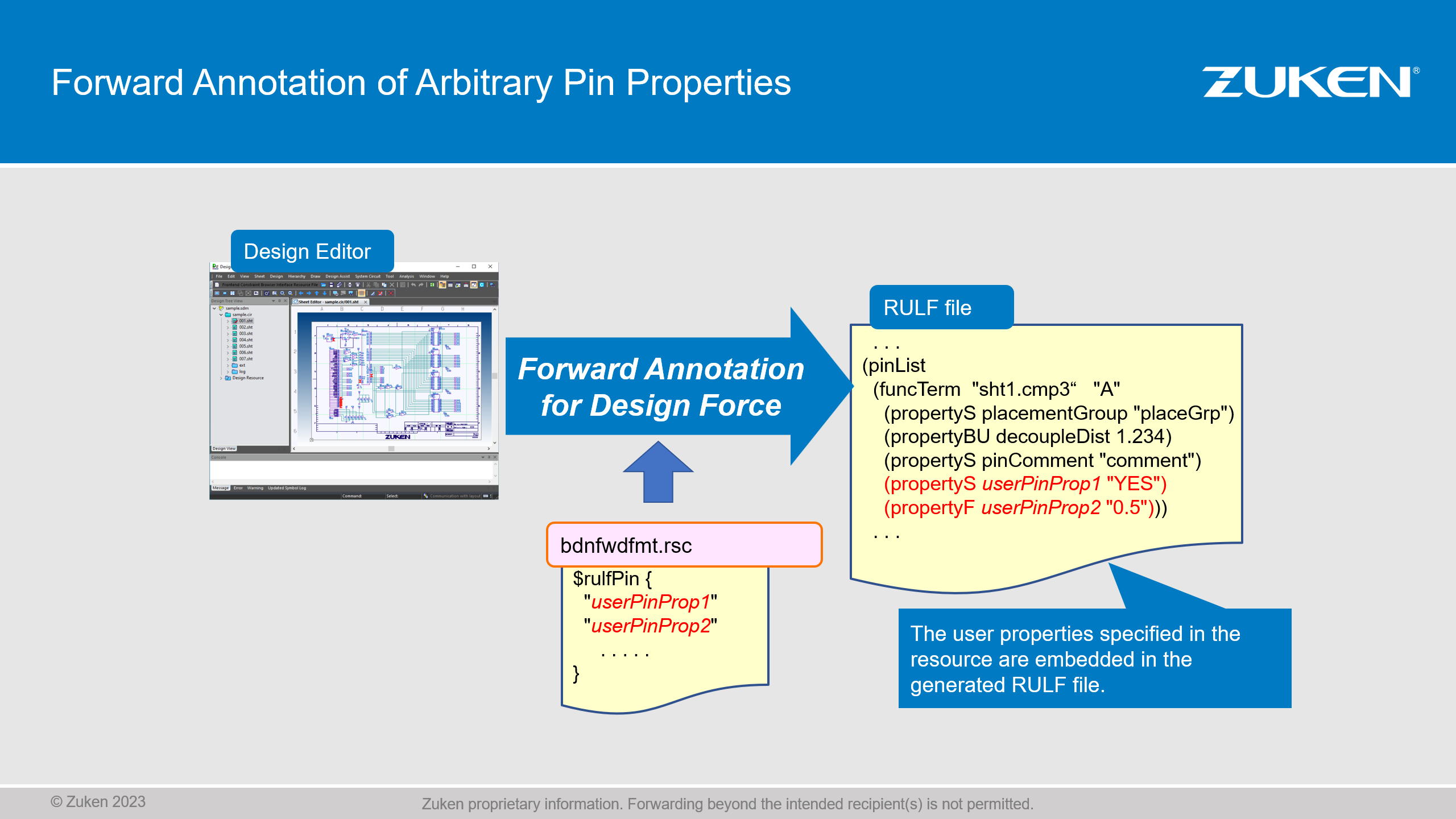
Communicate your design intent in customized annotations
CR-8000 Release 2023 simplifies the communication of your design intent through customized annotations. You can enhance your design by incorporating additional pin properties, such as pin length and pin delay, to ensure accurate representation and clear communication. The user-friendly experience allows for easy entry of these properties using a resource file, streamlining the annotation process. These properties seamlessly transfer as layout instructions to CR-8000 Design Force, enabling you to bring your design to life with precision and efficiency.
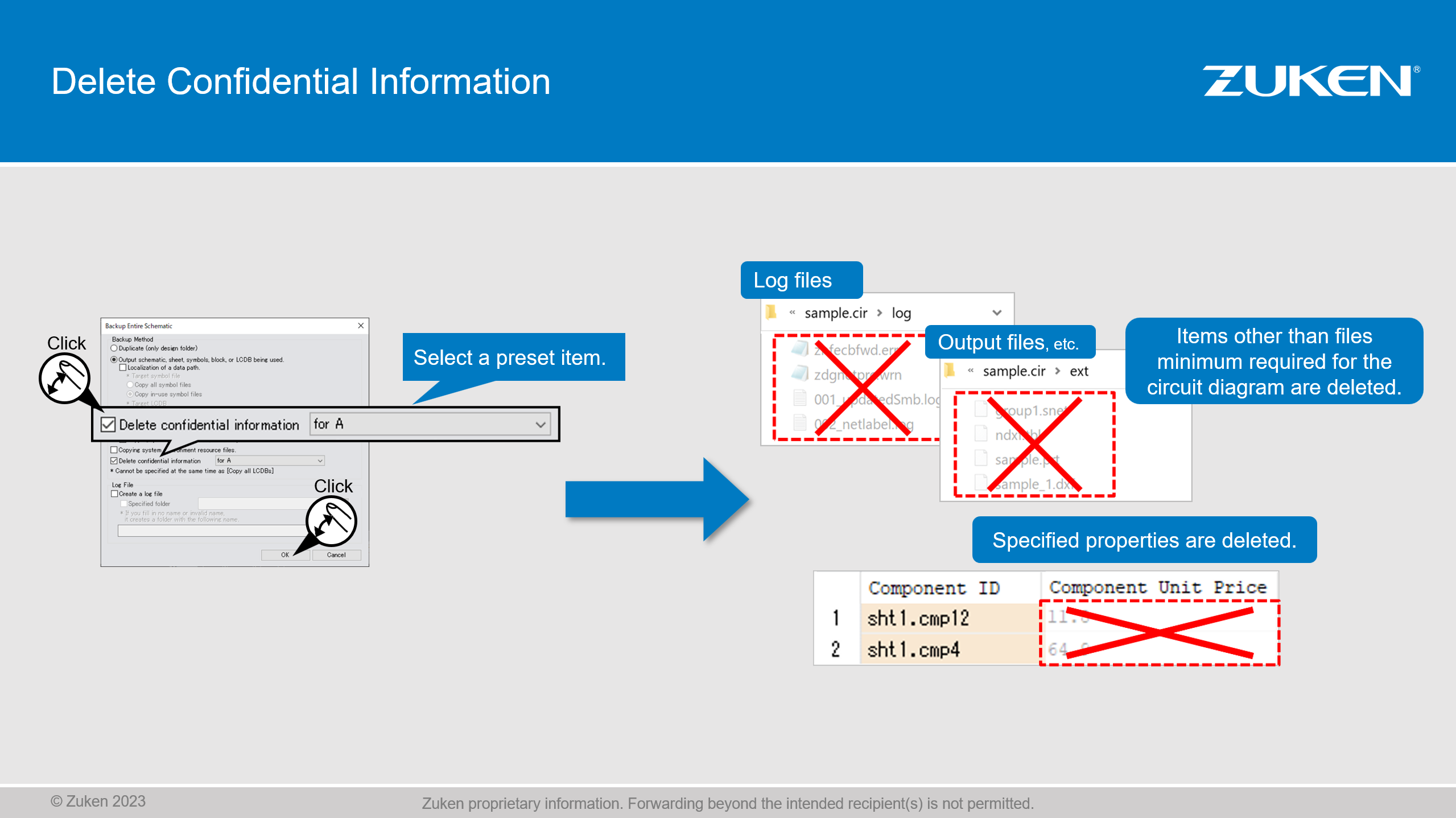
Remove confidential information before handover
This new feature provides extended control over the intellectual properties that are shared with external partners, offering increased security and protection. It allows for the removal of confidential information before handing over your design. Unnecessary files, arbitrary properties, and any items other than the minimum required for the circuit diagram can be excluded. Users have the ability to create multiple resource files to meet different requirements, such as for internal users or external service providers.
Reuse and edit circuits and text elements in your documentation
This new feature allows for the reuse and editing of circuits and text elements in your documentation. Circuits and text elements can be copied to the Windows clipboard, enabling their insertion into text documents. The inserted elements can be displayed in color or black/white as needed. The copied circuits can be edited to align with the specific requirements of the documentation, providing flexibility and customization options.
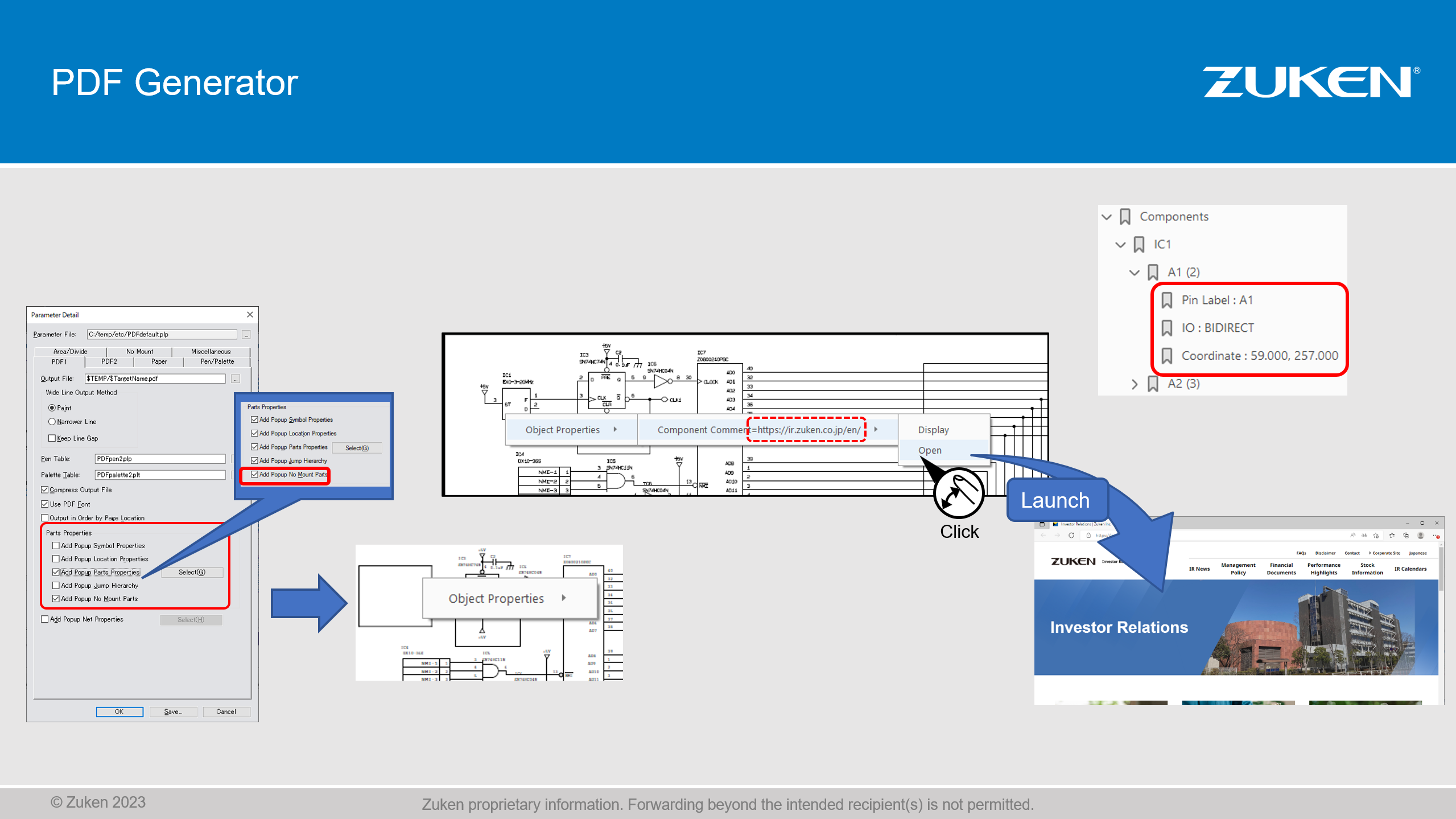
Create PDF outputs containing cross-references, bookmarks and URLs
Users can create PDF outputs with enhanced features, including cross-references, bookmarks, and URLs. By utilizing bookmarks, users can conveniently include additional information such as pin properties, symbols, location details, and external document URLs. These features significantly improve the usability and accessibility of PDF outputs, enabling efficient navigation and referencing.
Design Force
Apply mesh planes to your designs
Mesh planes can be generated within a template area and then automatically applied onto a conductor layer through an automated operation. When applied, the mesh planes are automatically adjusted to ensure the specified spacing between pins and tracks. Additionally, the mesh is intelligently generated around tracks of adjacent conductor layers, taking into account the proximity of adjacent layers. Users have the ability to define the distancing values between tracks and mesh, providing flexibility and customization options.
Control the area fill of patterns carrying no nets
A newly introduced feature offers users control over the connection of unconnected copper areas, specifically connectors that contain copper figures. Users now have the ability to decide whether an area should be connected or left unconnected. Our video showcases three possibilities for an example containing two copper areas: a) connecting both areas, b) connecting one and excluding the other, and c) keeping both areas unconnected. This feature provides users with greater flexibility and choice in managing the connectivity of copper areas within their designs.
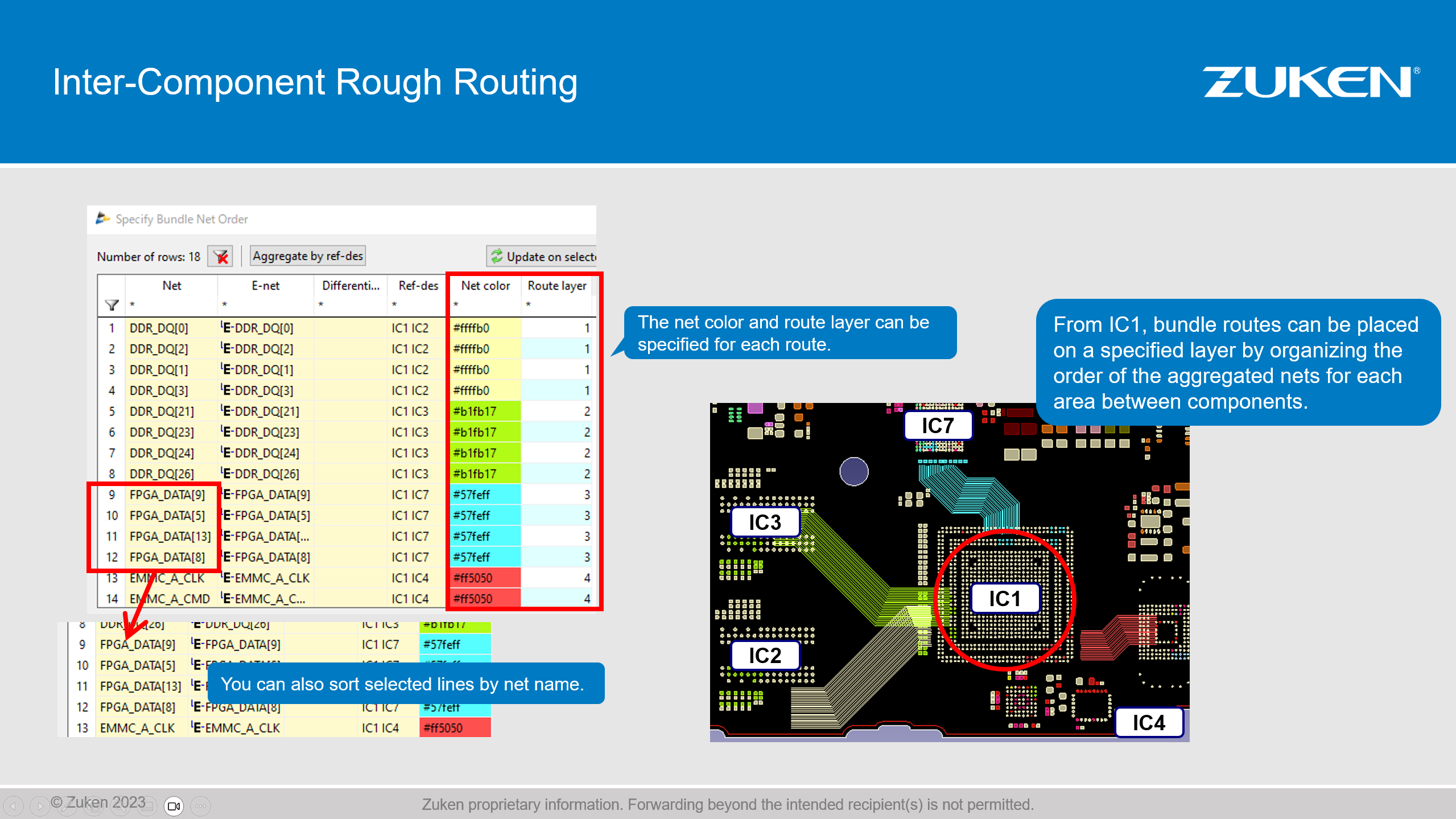
Aggregate and organize nets before routing
This new feature allows for the aggregation of connections and nets by area, facilitating the tracing of rough routes between components. A dialog interface enables users to specify the net color and route layer to be utilized for each group of connections. Moreover, the dialog provides options to sort connections in both alphanumeric and interactively defined orders. By defining a predefined order, users can initiate bundle routing directly without the need to individually select the related connections.
Automatically follow existing routing patterns
A new interactive contour routing feature enables the automatic following of existing routing patterns. Users can sketch a track or a differential pair along a designated layout area or other existing lines, such as tracks. This functionality allows for seamless alignment with established routing patterns, streamlining the routing process and enhancing overall design consistency.
Reuse template areas
The reuse of template areas is a valuable new feature that enhances productivity and consistency in designs with multiple channels. In such designs the placement and routing patterns can now be automatically propagated to all other blocks. This automation saves significant time and effort by eliminating the need for manual replication of patterns across multiple channels. By reusing template areas, designers can ensure consistency in placement and routing, leading to improved design quality and efficiency.
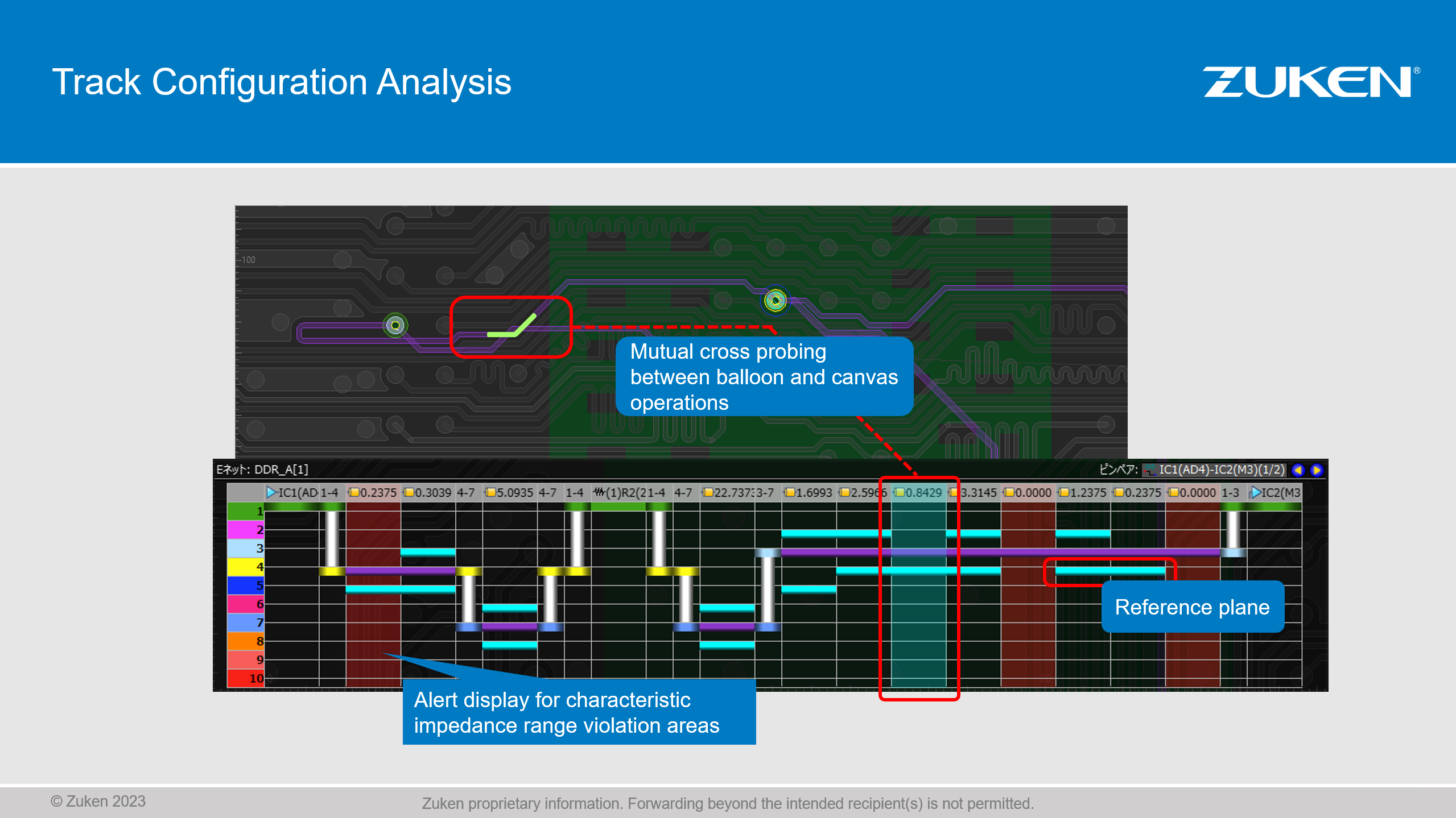
Analyze track configurations in cross section displays
Users can examine the routing of a trace path by visualizing a cross-sectional view that showcases the trajectory across various layers. This capability allows for comprehensive inspection and evaluation of track arrangements, aiding in identifying potential issues and optimizing the design. By providing a detailed representation of the trace path, designers can gain valuable insights and ensure the desired performance and integrity of their circuitry.
Automate the generation of silk screen text
Component symbols can be conveniently generated in a batch operation, utilizing specified values for clearance and incorporating positional relationships as needed. This automation streamlines the process of generating silk screen text, saving valuable time and effort for designers. With the ability to quickly and accurately generate component symbols, users can enhance the efficiency and consistency of their designs.
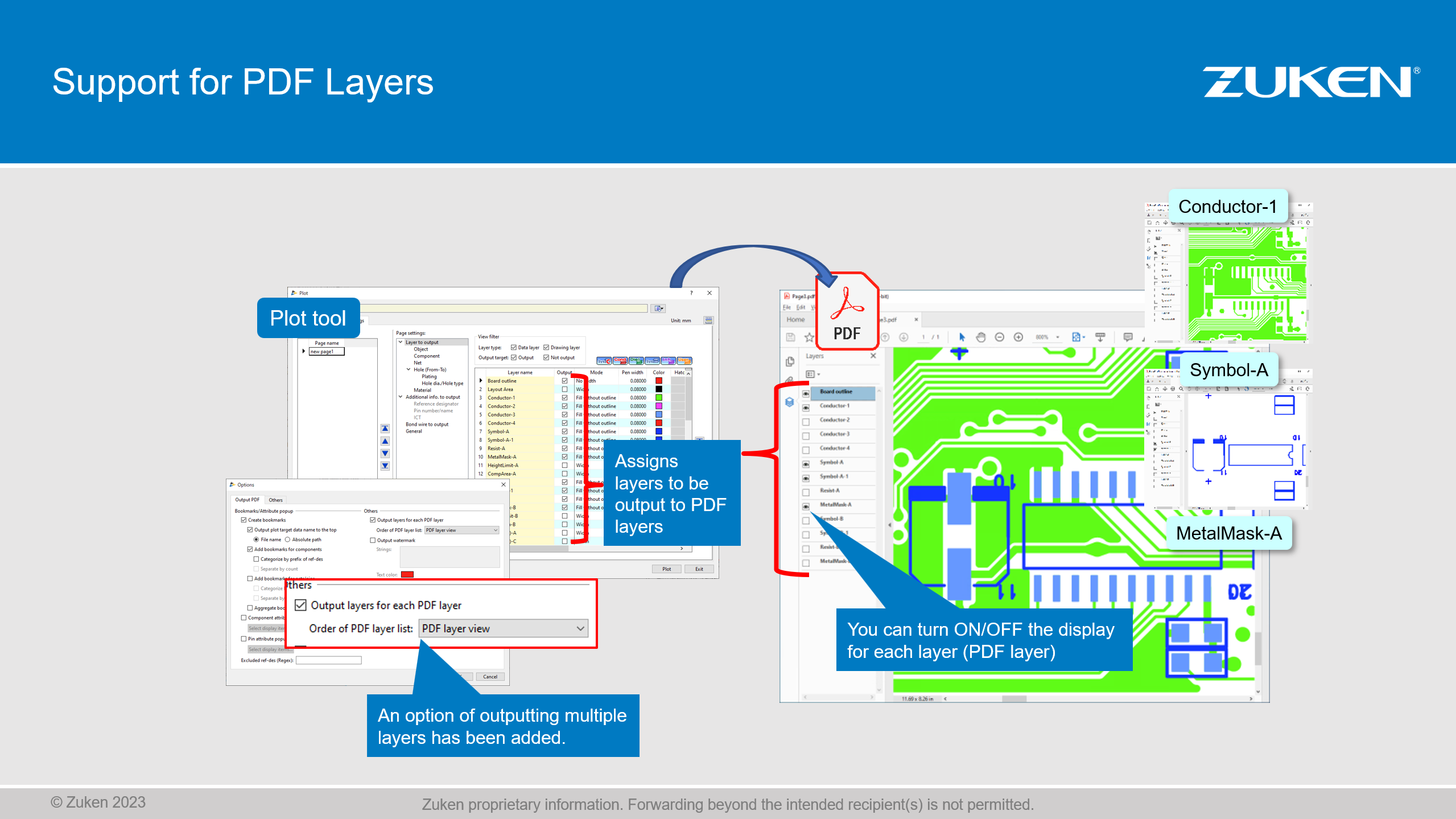
Create interactive PDF outputs of your PCB designs
This new capability allows the creation of PDF files that provide an interactive experience by enabling the ON and OFF toggling of layer displays. Users can selectively control the visibility of different layers within the PDF, enhancing the flexibility and convenience of sharing and reviewing design files. This interactive feature empowers users to effectively communicate and collaborate with stakeholders, facilitating a more efficient and dynamic design review process.
Design Force Analysis Advance
New bundles and extended functionality
The CR-8000 SI, PI, and EMI analysis tools have been consolidated into two powerful product bundles: Design Force SI Advance and Design Force PI/EMI Advance. These bundles bring numerous enhancements, including improved graphical user interaction, boosted performance with MultiCore CPU support, and the ability to handle large data quantities and perform parallel processing using a 64-bit computing architecture. The introduction of AI/ML-assisted S-Parameter modeling provides easy-to-use and accurate system-level SI- and PI Analysis. New Power Integrity constraint checks further augments the capabilities, enabling concurrent design and analysis.
Signal Integrity Analysis
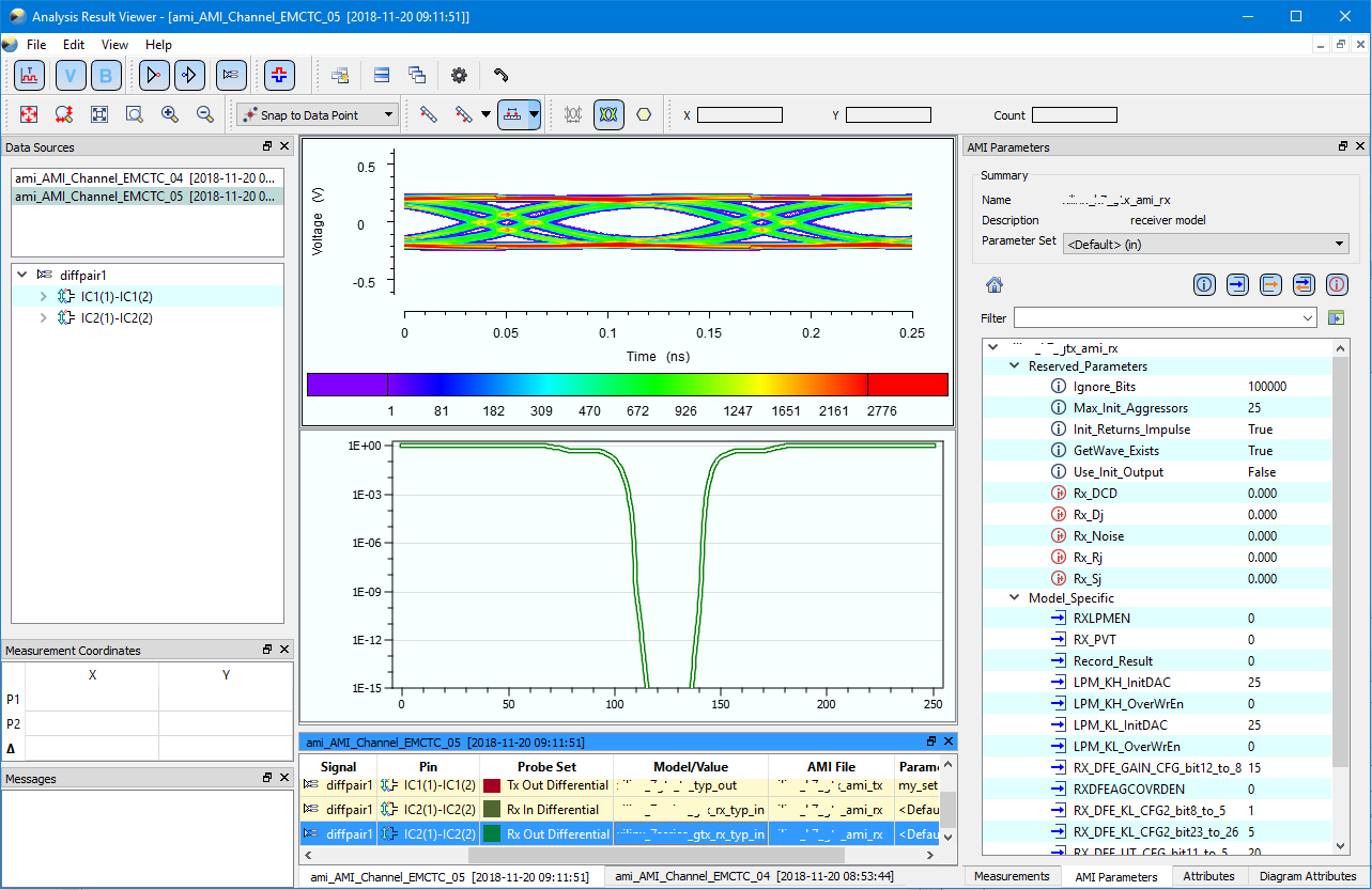
Design Force SI Advance combines a range of new functionalities to enhance your signal integrity analysis capabilities. This new, comprehensive bundle covers all aspects of Signal Integrity from Characteristic Impedance to IBIS AMI analysis of SerDes channels.
- A user-friendly Electrical Editor facilitates easy creation, inspection, and fine-tuning of topologies. Whole modules can now be imported, visualized, and simulated directly from the Electrical Editor supporting the IBIS EBD description. A built-in Configuration Editor enables exploration of manufacturing and material tolerances of PCB connections aside a wide variety of what-if scenarios of different transmission line technologies.
- A Lossy Transmission Line model considers copper surface roughness for fast and accurate analysis, yielding precise results, which now also contains the package-level power awareness of recent IBIS buffer models.
- Integration of IBIS, SPICE, and S-Parameter models in both time- and frequency domain enables comprehensive system-level analysis. Workflow efficiency is improved with automated Time Domain Reflectometry (TDR) and Eye Pattern analysis.
- Last but not least, a comprehensive HSPICE export and the ability to calculate and export S-Parameter Touchstone data for interconnect structures opens the door for even more advanced analysis steps.
PCB-level EMI and Power Supply System Analysis
Design Force PI/EMI Advance provides powerful capabilities for PCB-level EMI and Power Supply System Analysis. It offers a fast estimation of worst-case electromagnetic emissions, taking into account the PCB, attached cables, and heatsinks, covering both Common-Mode and Differential Mode emissions.
- Power Integrity features include the computation of IC power pin impedances, enabling users to check against chip vendor constraints.
- Design Force PI/EMI Advance considers VRMs, the location and (parasitic) values of Decaps, and the numerous plate capacitors created by overlapping power- and ground planes. Decap impedances are automatically computed and evaluated regarding their effectiveness, while considering package sizes. S-Parameter based models can alternatively be used.
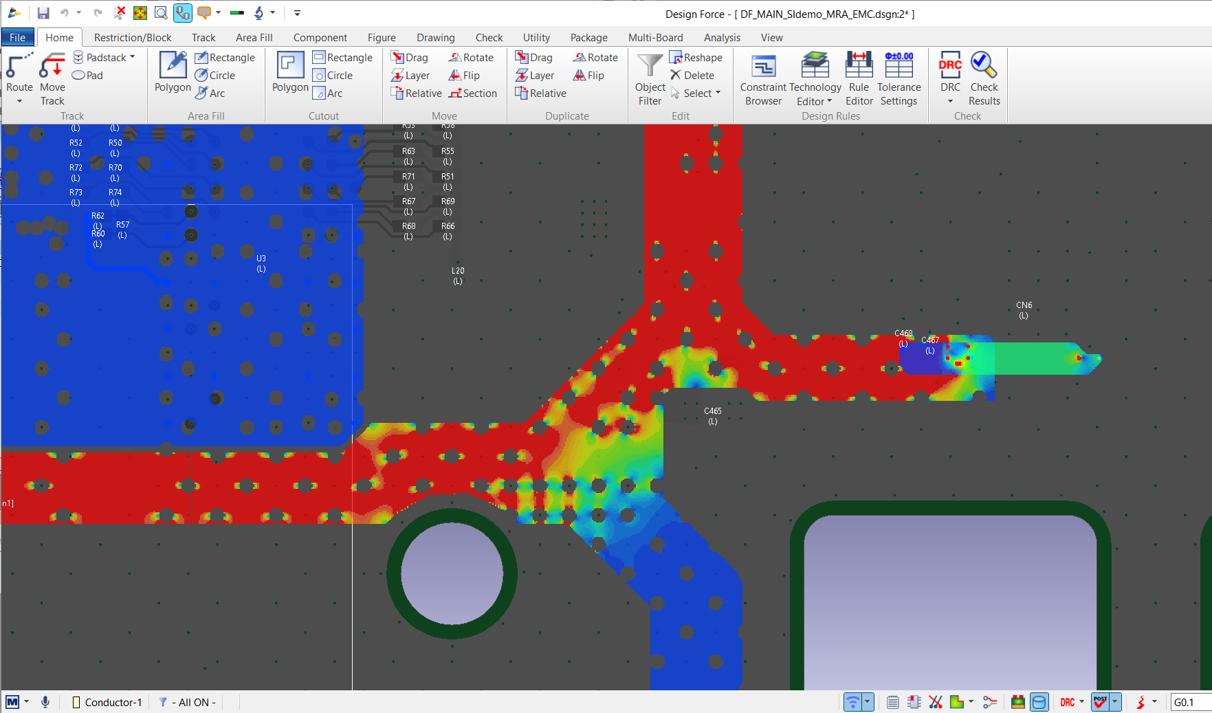
- A rapid yet accurate DC analysis is available for detailed assessment of voltage and current distributions within the supply system. This analysis encompasses factors such as IR-drop, Via currents, and IC supply voltages. Constraint violations of these quantities can be visualized easily
- A Lossy Transmission Line model considers copper surface roughness for fast and accurate analysis, yielding precise results, which now also contains the package-level power awareness of recent IBIS buffer models.
- Integration of IBIS, SPICE, and S-Parameter models in both time- and frequency domain enables comprehensive system-level analysis.
- Workflow efficiency is improved with automated Time Domain Reflectometry (TDR) and Eye Pattern analysis.
- Last but not least, a comprehensive HSPICE export and the ability to calculate and export S-Parameter Touchstone data for interconnect structures opens the door for even more advanced analysis steps.