
Place Components and Symbols
Placing and navigating between components can easily be done by working in the Devices Tree View of the Project Window and the Component Tree View of the Database window.
Regarding the placement of any objects in the drawing, user- and project-specific settings can be defined in Tools -> Settings -> Placement.
To find more information on placing devices, symbols and subcircuits, please see also:
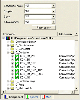
Searching the database
The list of available devices can be reduced by specifying various selection criteria (namely: Description, Component Type, Supplier and Technical Data). See also Component Search Configuration.
To place an independent symbol
Symbols, that are found as part of a Component in the Component Window, can be placed independently of a component.
Right-click on the desired part of the component in the Tree View (Check that it is the correct symbol in the Preview Window) and select Place as Symbol from the displayed context menu.
Move the cursor onto a drawing sheet and left-click/use the Enter key to place the symbol. The symbol is placed in the drawing independently and has no connection to a Component or Device. It is recognized internally as an unassigned 'electrical' symbol.
To place symbols on existing lines
Placing symbols on existing connection lines is only possible if:
-
the direction of the orthogonal connection lines corresponds to the orientation of the symbol and its connect points.
-
Only one symbol is selected (regardless whether it is a new symbol or an existing one that has been moved or copied).
If a symbol can be placed on a connection line, the original connection will be modified as follows:
-
The line will be split to accommodate the symbol.
-
The properties of the new connection segments correspond to the existing connection.
-
When the connection is split into several segments, the following priorities are valid for the existing conductor numbers:
-
Signal (user-defined)
By inserting a symbol with already pre-defined signals, it may happen that one segment contains a user-defined signal, the other segment contains a system-generated signal (#nnn). In this case, the connection segment with the user-defined signals gains higher priority. When both of the connection segments have a user-defined or system-generated signal assigned, the next priority level applies.
-
Connection Cross-References
When one of the two connection segments contains a connection cross-reference, this side gains higher priority. When both segments contain a cross-reference, or none at all, the next priority level applies.
-
Attribute Indicator Symbols
The connection segment that contains the higher number of attribute indicator symbols placed gains the higher priority. When the same number of indicator symbols is placed on both sides, or none at all, the next priority level applies.
-
Line Segments
The connection segment that contains several line segments, gains higher priority. When both sides have the same number of line segments, the next priority level applies.
-
Pin Position
The side whose pin is placed on the upper left, gains higher priority.
-
-
The existing signal name, assigned automatically by the system, is retained on the larger net if a connection is split into several segments.
This order defines which side of a split connection gains higher priority and thus keeps the existing wire/hose placed.
When placing a symbol of a default device with and without mating connector definition, of a connector or connector symbol or a terminal in a connection, conductors / wires are split, duplicated and placed on both sides.
When a device/symbol is placed into an existing connection containing a wire / hose, the existing connect line is split in two parts.
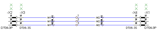
Example
Wires before separating:
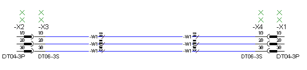
Wires after separating:
To place symbols as graphics
Symbols, that are found as part of a component in the Component Window, can be placed as simple graphics.
Right-click on the desired part of the component in the Tree View (Check that it is the correct symbol in the Preview Window) and select Place as Graphic from the displayed context menu.
Move the cursor onto a drawing sheet and left-click/use the Enter key to place the symbol. During placement, the symbol can be rotated and mirrored by right-clicking to display a context menu. The symbol is placed as a grouped graphic.
Alternatively, a selected symbol can be inserted into a drawing by selecting the Insert -> Graphic -> Symbol command on the Main Menu bar, the selected symbol is loaded into the symbol buffer before placing it.
If, in Database Editor mode, a symbol is placed using the Place as Graphic command, only completed text nodes are taken over. These texts are always created as text type 11 and, if required, shortened to the max. allowable length.
Graphic text copied onto a DBE symbol sheet (from a project sheet), is also created with text type 11 and shortened to the max. allowable length.
Grouped/bound graphics copied onto a DBE symbol sheet is ungrouped/unbound.
To place symbols as models
Symbols being part of a component in the Component view of the Database Window, can be placed as models in Database Editor mode. This is, however, only possible in case no other model has been placed yet on the drawing sheet.
Right-click on the desired symbol of the component in the tree view and select Place as Model from the displayed context menu. The system checks whether it is possible to place the model.
Move the cursor onto the drawing sheet and left-click/use the Enter key to place the model. During placement, the model can be rotated and mirrored by right-clicking to display a context menu.
To place unused symbols of existing devices
Use the Devices Tree View of the Project Window.
Locate the desired device in the Devices Tree View and left click on the '+' box adjacent to the device, to open the device's own tree. All parts of the device are now displayed with already used parts indicated by blue icons and unused parts by yellow icons.
-
Left click on the desired unused part to select it and the symbol is displayed in the Preview Window
-
hold the mouse button down and drag the symbol to the drawing sheet and release the button to place the symbol, or
-
right click on the desired unused part and select the Place command from the displayed context menu
-
The symbol in the Devices Tree will change to a blue icon and the location reference is added (e.g.: sheet 3, section C2).
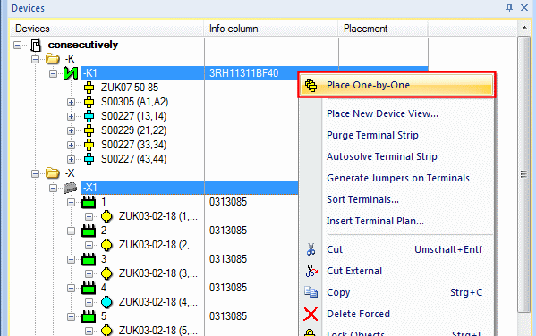
Placing several unused symbols consecutively
To place several symbols on a worksheet one-by-one
-
select the desired symbols (multi-select also possible) in the Device Tree
or select a superordinate object
-
right-click on the last object to be selected
-
select the Place One-by-One command in the displayed context menu
-
Now begin placing the selected symbols! All unplaced symbols appear at the cursor position to be placed one by one.
Note
-
The current symbol to be placed is displayed in the Status line:
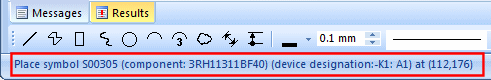
-
It's possible to jump over the current symbol to be placed using the N key.
-
The command can be aborted using the Esc key. In the meantime, the placed symbols remain in the schematic.
Multiple placement of the symbol selected last
-
... use Hotkey D ...
To place new devices
Use the Component Tree View of the Database Window, selected with the appropriate tab,
-
select the desired component (observe the Preview Window and the Status bar),
-
click either on the component or to select a specific part of the component, click in the '+' box to open the component's tree, and then click on the desired part,
-
drag the symbol to a sheet window,
-
release the mouse button and the symbol will be placed in the drawing.
-
A new item designation is automatically created depending on the definition in the database.
-
When part of a Component is placed in a drawing, a complete new device is added to the project and can be seen in the Device View of the Project Window along with the location of the placed part.
During the drag operation
-
any displayed but not active window will pop up to the top if you move over the window,
-
any zoom area of the current (active) window will move if the mouse reaches the edge of the window.
Look at the Devices tab in the Tree View window: A new entry appeared...
Multiply insert a component
Components from the database tree can multiply be inserted to the device tree.
For this, use the command ![]() Insert Multiple
Insert Multiple
Note
-
The Insert Multiple command doesn't appear for components without symbols nor for subcircuits.
-
The Insert Multiple command can also be used for several components that have been selected with multi-select.
To insert a component multiple times in the Device Tree
-
right-click on the desired component in the Database Tree,
-
select the new command Insert Multiple from the displayed context menu
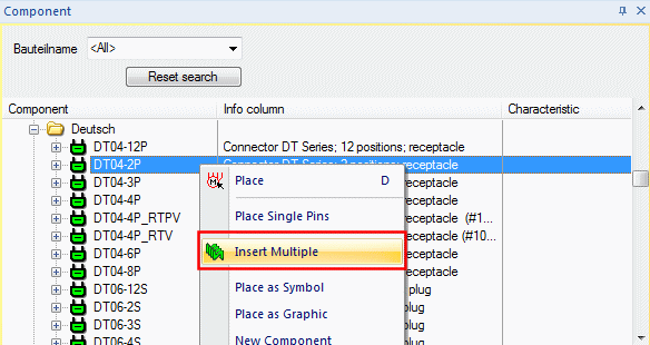
-
this opens the new dialog Insert Multiple:
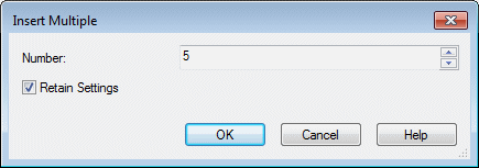
|
Insert Multiple |
|
|
|---|---|---|
|
Number |
The number of devices that shall be inserted in the Device Tree for this component are defined in this field. |
|
|
Retain Settings |
If checked, the value entered under Number: is reused the next time with the Insert Multiple command. |
|
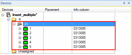
Afterward, the devices are loaded in the Device Tree:
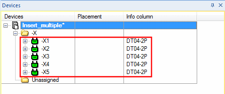
Furthermore, a list of the devices that have been loaded into the project are displayed in the Message Window.
Note
Inserting multiple terminals results in a terminal strip being generated, on which all can be inserted.
Using higher level assignment and location of the sheet/field on placement
When placing a component, it can automatically be assigned the higher level assignment and location of the sheet/field by activating the option Use higher level assignment and location of sheet/field in the Placement tab of the Settings... dialog. The option is also valid when global settings for the sheet/field already exist.
It has a higher priority, i.e. if the option is active, higher level assignment and location are always taken from the sheet/field (even if nothing has been assigned). This makes it easy to create sheets with definitions for Higher level assignment and Location corresponding to the global settings and subsequently place components on these sheets with the same definition.
When the option is activated, and a corresponding component is to be placed on a sheet with another definition, this is possible without deleting the global settings.
Higher level assignment and location of the sheet/field are used, if
-
new components are placed directly from within the Component Tree View of the database,
-
the first symbol of a component is dragged from the Device Tree View to a corresponding sheet
Higher level assignment and location are only allocated, if the component has not already been assigned a higher level assignment / location. Existing definitions will not be changed due to this option.
Remaks
-
When placing from within the Database tree onto a sheet, the Tools -> Settings -> Placement -> Use higher level assignment and location of sheet/field option has higher priority than the default values for the higher level assignment and location designation. When the default values for higher level assignment and location are assigned to a component, for example by dragging & dropping into the Device tree, these default values remain valid also when placing from within the Device tree onto a sheet with higher level assignment and location assigned.
-
When the component already has a device designation assigned and is then, through sheet definition, assigned a higher level assignment / location, the device designation remains unchanged, provided that this will not result in a duplication, i.e. devices now having the same device designation, higher level assignment and location. In case a duplication would arise, a new item designation would be created.
-
When placing a component of an assembly from the database, the higher level assignment and location of the assembly, and thus all devices of this assembly, are specified by the first symbol that is placed.
This is independent of the settings for the respective device in the assembly.
Placement from within the Component Tree View
With the above-mentioned option active, higher level assignment and location of the sheet will be used when components are placed directly from within the Component Tree View.
The option is available for the following objects:
-
normal components
-
terminals
-
connectors (complete, pin group, individual pins)
-
blocks
-
block connectors (complete, pin group, individual pins), provided that the related block has no higher level assignment / location
-
creation of components through placement on a panel sheet
A dialog box is displayed when creating a mount, a cable duct or a block. If the option is active, the default values of the current sheet are shown in the entry fields for higher level assignment and location.
If, during placement of the block, you change to a sheet with other definitions, the block will maintain the values set in the dialog.
Placement from within the Device Tree View
With the above-mentioned option active, higher level assignment and location of the sheet will be used when placing the first symbol of a component from the Device Tree View.
The following applies:
-
The system checks whether no symbol of the component has been placed so far (also variants and views).
-
Potential duplications are handled as if components with identical device designation and the same higher level assignment/location existed already, i.e. new Item Designations are assigned.
-
Depending on the option the higher level assignment and location of the sheet are also taken over, if a component, connector or block is placed from within the tree view which results in the devices being renamed due to the 'extended' designations.
Note
-
If the item designation already contains a higher level assignment and location, the component is not assigned those of the sheet.
-
Component views and models are handled like the original component. If for example a model is placed on a panel sheet not bearing a higher level assignment/location yet, the complete device, i.e. the base component of which symbols are already placed in the circuit diagram, is correspondingly adjusted.
-
As variant instances of a component can be created independent of the standard component, they will be renamed after placement; the item designation of the standard component and other variant instances remain unchanged. This may result in different names within the dependent variants of a component. Their dependencies between each other might not be clear at that time. To ease this problem, no new automatic item designation will be created in the case of name conflicts with variants.
-
Standard components with variant instances and variant instances will not be renamed and keep their original names.
-
This option applies only to placement of schematic symbols and panel models, not for the placement of cables, conductors or wires.
To insert cables
Select the Insert -> Cable command to display the cable dialog menu. It can be used for defining cables on-the-fly and adding them to the project.
The Devices Tree View of the Project Window displays both cables that have been added to the project.
To directly insert a cable without having to fill out the dialog box,
-
select the desired cable in the Component Tree View of the Database window,
-
drag it to a Device Tree window,
-
release the mouse button and the cable will be added to the project. The individual conductors can then be assigned to individual connections.
Alternatively,
-
select the desired conductor of a cable in the Component Tree View of the Database window,
-
drag and drop it onto a connection line in a sheet window
-
release the mouse button and the conductor will be assigned to the connection and complete cable will be added to the project.
To place wires and shields from within the Database Window
In a Tree View (Device Tree View, Component Tree View or Misc Tree View of the Database Window),
-
select the desired shield or wire,
-
drag it to a sheet window (or right-click and use the Place command from the object menu),
-
release the mouse button and the shield or wire will be placed in the drawing.
-
In case a wire or wire group is to be placed using the Place command from the context menu, the selected wire / wire group will be listed in the Device tree view of the project window and can then be placed in the drawing.
To be able to drag a shield symbol from the Device Tree View or from the Component Tree View onto the sheet, a default shield symbol has to be defined for shield symbols (Tools -> Settings-> Placement->Symbols->Shield Symbol).
If the shield of a pre-defined cable component, is placed within the Device Tree view, or Misc. Tree view, the shield-wire structure remains unchanged. If shields of a cable, generated dynamically, are placed from within the Device Tree view, the shield-wire structure remains unchanged. However, when a shield is dragged from the Misc tree view over conductors of a cable generated dynamically, the shield-conductor structure changes, depending on the conductors currently shielded by the shield symbol.
When placing a shield symbol on a sheet, the system checks which conductors lie under the shield symbol. The shield will then be assigned to that cable and, in the case of dynamic cables, added correspondingly to the Device Tree View. Relevant text, e.g. Device Designation, is displayed on the symbol. If the shield symbol does not cover the required conductors, right-click on the symbol, select the move handle of the symbol and stretch the symbol to the required size, or select them and move them to the required location.
If the shield symbol covers conductors of different cables, then the shield is not assigned to any cable.
To add a new view of an already existing shield symbol to the project, place the shield symbol on the same conductors that are already covered by the first shield symbol.
A selected shield can be assigned to a cable that already exists in the project. To do so, right-click on the shield and select the Symbol Properties... command from the displayed context menu. The Device Designation field in the Symbol tab allows you to select the cable to which the shield symbol is to be assigned.
To place bundle symbols
After selecting a cable bundle or a cable it is possible to select the Autoplace Bundles command from the context menu in the Device tree.
The bundle symbols defined in the Settings... are placed on graphic connection lines, on which the conductors are placed.
Placement distances are defined in Settings... -> Placement -> Symbols -> Bundle Symbols in the section Parameters for automatic placement:
-
Minimum distance to pin: Minimum placement distance to the next conductors' pin.
-
Minimum distance between bundle symbols: Minimum distance between bundle symbols.
-
Line overlapping: This value defines the placement position below and above the symbol; the value is determined symmetrically.
This command is only executed, if a bundle symbol has not been placed on the bundle yet.
Note
Symbols are placed on graphic connections of the original view as well as on all graphic connections of the views.
Graphic connections of the pin views are not considered.
Regarding multiple bundles (bundle in bundle), the symbols are arranged next to each other as long as it is possible due to the distance.
To place signal cross-references
Select the Misc tab of the Database Window,
-
select the desired signal cross-reference and
-
drag it onto the drawing sheet,
-
release the mouse button and the reference will be placed in the drawing.
There are two different options for placing signal cross-references:
-
1st option
The symbol is placed independently on the sheet. A unique, consecutive, identification number is determined.
Later, when a connection is made to the symbol, the signal assigned to the connection is shown on the symbol.
Note:
When moving a signal cross-reference, you have to select it by placing the cursor over the connection point of the symbol).
-
2nd option
The symbol is placed directly on an existing open-ended connection line, the signal assigned to the connection is shown on the symbol.
The properties of signal cross-references can be changed in the Sheet References dialog box.
To place pins one upon the other
There are devices, that are plugged one upon the other, but can also be normally connected to the same pin (with mating connector).
Normal symbols with or without component assignment can be plugged one upon the other.
This can be done using Place and Move, Drag&Drop and Copy&Paste, as well as when importing subcircuits.
The existing plug connection is signal transferring and exclusive (i.e. no other connection is possible).
Note
Regarding the placement of pins one upon the other, the following applies:
-
Placing unconnected pins on pins of Promis or DDS-C import does not affect the unconnected pins. The Update in project command on symbols is executed with the system displaying a message.
'Place as Graphic' to create a graphic view with assigned texts for item designation and pin name
To get a better overview over the display of parts of a drawing, it is possible to display, for example on signal cross-references, not only the target device but also the graphic of the target symbol using the Place as Graphic command.
The symbol is placed as graphic only, with the pin names, the item designation and other attributes being available online, since these can change. Therefore these attributes always show the current value.
When the "original symbol" is deleted, the graphic remains existing.
The Place as Graphic command can be executed on a sheet when exactly one symbol or connector pin was first copied using the Copy command or Ctrl+C. The command is always available on a symbol or connector pin in the project tree, regardless of first having copied or not.