Placing Attribute Template Symbols
Attribute text template symbols can be placed on any position to display project and component attributes.
Definition in Database
Default Template symbols can be defined for normal components, connectors, cables, blocks and assemblies in the database:
-
To define them, simply place an attribute template symbol on the respective component sheet. Attribute template symbols are available in the E3.series standard database in the Misc tab.
-
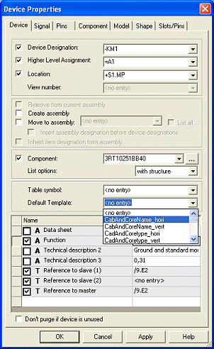
The Default Template can also be selected in the Component Properties... dialog.
Note: The Default Template can only be defined for hoses/wires.
-
The default template symbol is saved in the component attribute .DEFAULT_TEMPLATE in the database.
Definition and Usage in Project
The Device Properties... dialog also contains a selection list for the Default Template, in which the defined default template symbol is displayed and if necessary, can be changed.

This functionality is especially useful when defining and placing template symbols for dynamic components.
In project mode it is possible to
-
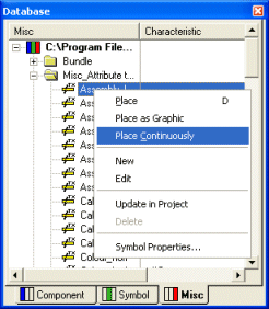
place attribute template symbols from the database tree's Misc tab into the schematic. In this case the template symbol is not assigned to a component and may only describe project attributes.
-
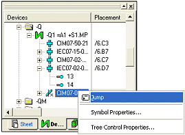
place attribute template symbols using the Place Attribute Template command in the Device Tree context menu (on components, connectors, cables, blocks and assemblies).
This command is only displayed if the selected component, connector or cable type is assigned a template symbol. A template symbol can be assigned using the Default Template option in the Device Properties... dialog box.
In this case, the symbol is directly assigned to the device and displays information corresponding to the contained texts.
Attribute text templates of devices of the type cable or cable bundle that are placed on connect lines, only show the information of the
Attribute text templates of cables and
Attribute text template symbols that for example use the text type Cable in connection show the busbar's item designation. The text type
When attribute text template symbols show properties that do not exist for busbars or busbar connections, nothing is displayed.
Display and Navigation in Device Tree
After placing, the attribute template symbols are displayed in the device tree view as follows:
-
after the last symbol with normal components;
-
after the last pin group or last pin with connectors;
-
after the last bundle or last conductor with cables;
-
after the last contained component or the last sub-assembly with assemblies;
-
after the last block connector with blocks;
-
in the Unassigned folder in the project.

Navigation in the device tree view:
-
Double-clicking jumps to the schematic. This functionality is also available using the Jump command in the context menu.
-
Using Jump to Tree on the template symbol jumps to the tree structure.
Modification of Template Symbols
Template symbols can be exchanged by other attribute template symbols, that may contain different texts, at anytime through the Symbol Properties... dialog.
Note
-
It is only possible to delete an object assigned a template symbol, if the object does not have any other template symbols assigned.
-
Changes made to an object containing a template symbol are immediately displayed in the template texts.
-
When executing Update in Project on components, existing template symbols are not considered.
Changing the Template Properties
Attribute template texts, which are linked to attributes, can be edited directly on the sheet through the Text Properties... or by simply pressing F2. This results in the corresponding attributes being changed.
Placing Attribute Template Symbols on Net Nodes
To be able to assign properties to net segment nodes in E3.formboard, e.g. for sealings, T-parts etc., it is possible to place attribute template symbols on net segment nodes.
Texts are correspondingly filled with attribute values of the net segments or with those of the complete net (in case no corresponding attributes are available for the net segments). Conductor information is displayed by the conductors that are placed on these nodes.
When moving connect lines, with which the net node is also moved, the attribute template symbol is also correspondingly moved.
See also: Formboard Functionality - Overview
Placing Several Attribute Templates onto Several Connect Lines using 'Place Continuously' Command
The Place Continuously command is available for attribute templates and for components containing attribute templates. Therefore it's possible to place attribute templates onto several connect lines.
Please select the Place Continuously command through the context menu on a attribute template in the Database tree view.

After executing the command the attribute template is displayed on the cursor. Using the left mouse button the symbol can be placed onto the sheet. By keeping the left mouse button pressed and moving the mouse, a horizontal or vertical line can be created.
By additionally pressing the Shift button the line is created diagonally. When releasing the left mouse button attribute templates are placed onto each point of intersection.
The command can be aborted by pressing the ESC button.
Note
-
Placing on orthogonal connections
Symbols are placed the way they are defined in the database. When rotating while placing, the rotation remains existing and the symbol is placed the way it appears on the cursor. Therefore, it is possible to, for example, define separate template symbols for the horizontal and vertical display.
-
Placing on angular connections
Independent of the symbol's rotation with which it was placed on the sheet, it is re-rotated according to the database definition. Then the symbol is rotated according to the connect line's angle.
Note: Rotations > 0° and < 90° and the rotations > 270° and < 360° are considered with angular lines. This rotation is directly transferred to the symbol.
When the symbol is rotated while appearing at the cursor, this rotation is considered for placement.