Device Properties - Device
To display/modify the properties of a device,
-
with the required device selected in the Drawing Window, select Format->Device Properties... from the Main Menu bar and select the Device View, or
-
right-click on a device on the drawing and select the Device Properties... command from the displayed context menu and select the Device View or
-
right-click on a device in the Device Tree View of the Project Window, select Device Properties... from the displayed context menu and select the Device View.
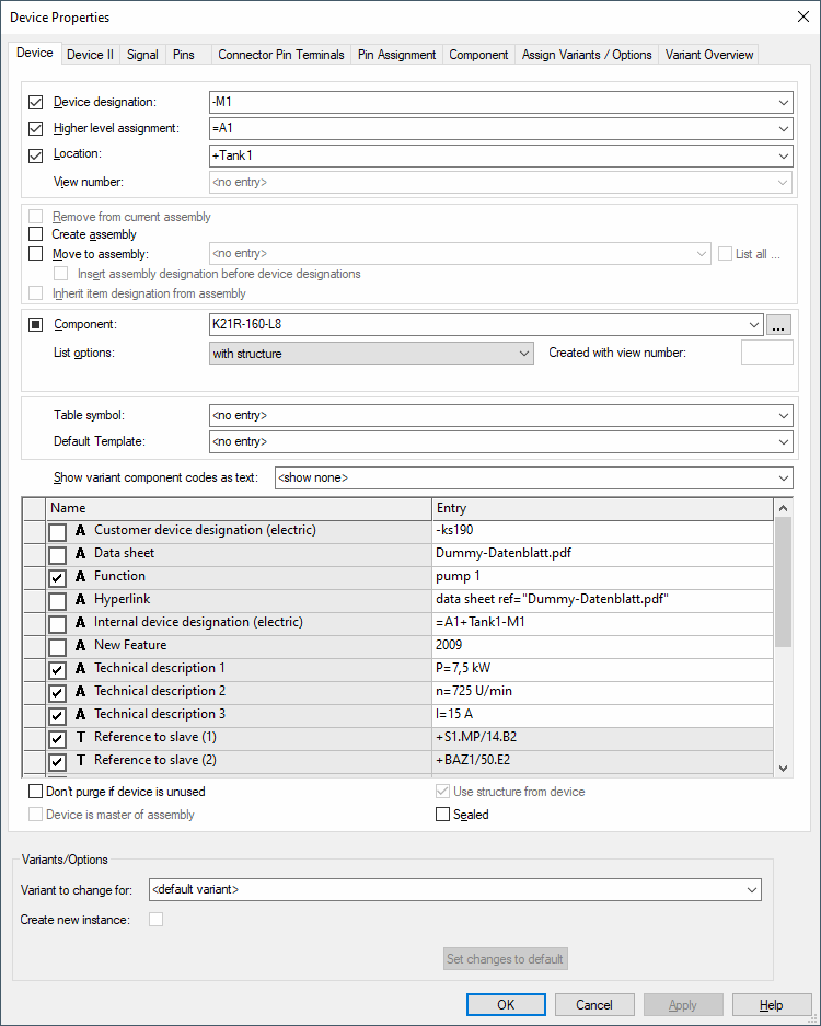
The following dialog box appears:

The dialog box comprises a group of entry fields (Device Designation, Higher Level Assignment, Location) for the definition of the ID block (i.e. the unique device ID), an entry field for the View number, an Assembly section, an entry field for the Component name, List options and the Table symbol, and a table for the entry of additional attributes.
When changes are made to the ID block, all occurrences of the selected device will be modified.
The checkboxes to the left of the Device Designation, Higher Level Assignment, Location and Component fields are used for controlling the visibility of the text for all symbols associated with the selected device. These checkboxes are inactive if the selected device does not have the corresponding text field associated with it. It is not possible to add device text in this dialog box.
The middle part of the dialog box contains the 'assembly' part.
The lower part of the dialog box contains the table for the specification of attributes.
To add additional attributes, select the empty Name field and left-click again to display a drop-down list box, displaying all of the available attributes for the selected device, from which a selection can be made. Attributes that can be used once only and have already been associated with a device, will not be displayed again in the list.
Select the Entry field to display a drop-down list box, containing all of the values that have already been used for that attribute within the project. If the required value does not exist, type in the new entry in the field.
Click on the Entry field containing a translatable text and press F3 to display the Translation Table dialog box. As in Database Editor mode individual columns can be sorted in ascending or descending order. Texts can be selected from the database.
Attention
The dialog box will not be displayed, if the entry field is editable (a field is editable, if the drop-down arrow is displayed at the right edge of the field).
The bottom part of the dialog is only displayed if variants/options have been defined in the project and the Standard Mode is active.
|
Device |
|
|---|---|
|
Device Designation |
A new Device Designation can be defined.
The new Device Designation is applied to all parts of the Device and the new designation is instantly updated on the drawing sheets and in the Device Tree view.
If a Device Designation is changed to one that already exists, an error message will appear to indicate the conflict.
The prefix '-' cannot be modified. It is predefined in Tools -> Settings -> Placement. |
|
Higher Level Assignment |
A new Higher-Level Assignment can be defined for the selected Device.
The prefix '=' cannot be modified. It is predefined in Tools -> Settings -> Placement.
If only the case of the designation is changed, for example =aaa replaced with =AAA, the system displays a prompt: The spelling of higher level assignment has changed. Do you want to change the name globally for this project? |
|
Location |
A new Location can be defined for the selected Device.
The prefix '+' cannot be modified. It is predefined in Tools -> Settings -> Placement.
If only the case of the designation is changed, for example +bbb replaced with +BBB, the system displays a prompt: The spelling of higher level assignment has changed. Do you want to change the name globally for this project? |
|
View number |
This option is only active on a device view.
Displays the view number of the selected device. |
|
Remove from current assembly |
This option is only active, when the device selected is part of an assembly.
A device can be deleted from an assembly. |
|
Create assembly |
Activate this checkbox to create an assembly (a combination of several components, even with different component types) and sub-ordinate the related component.
To add further components to the assembly, the same item designation has to be defined for these components.
To remove a component from an assembly, it must be assigned another item designation.
To rename the complete assembly, right-click on it in the device tree view and select the Rename command from the context menu (or press button F2). |
|
Move to assembly |
This option makes it possible to move a device to the selected target assembly in the drop-down list.
This option doesn't exclude Create Assembly because it is possible to add an assembly to another one. Thus the assembly is assigned as a whole to the target group (so it's not dissolved into parts and added to the target group).
All assemblies without component codes are displayed in the drop-down list. |
|
List all... |
The List all... checkbox lists all already defined assemblies in the list.
When this checkbox is unchecked, only assemblies whose higher level assignment and location agree with the current device, are listed. |
|
Insert assembly designation before device designations |
When creating an assembly and with this option checked, it is possible to hierarchically define the assembly designation before the designation of the assembly's parts.
This option is automatically active when using the IEC 81346 standard. The device is named as follows: -<Assembly>.<Name>.
The separator defined in Device Designation for IEC 81346 standard is used; otherwise "." is used. |
|
Inherit item designation from assembly |
This option defines whether the assembly should be adopted or the device retains its name.
Therefore, it's possible to have devices in an assembly with different item designations.
When this option is unchecked (default), the defined name is used. If the names collide, a new and unique name will be created.
If the same item designation is to be used, however, the Inherit item designation from assembly checkbox must be checked. |
|
Merge Harnesses |
This option is only available when the device selected is a harness in E3.topology.
The drop-down list displays all harnesses existing in the project.
Select the one from the list that is to be added to the harness selected in the Functional Objects tab of the Project window.
See also: Topology - Overview and Defining Harnesses |
|
A new component type can be defined for the selected Device. A check is made to ensure that the new component selected corresponds to the existing component, otherwise an error message is displayed.
Name-equivalent pins are changed along with the component type.
When changing the component of devices in project, the pins' signals are not changed.
Changing component of connected complete connectorsComplete connectors connected to a mating connector can be exchanged without restrictions, if the new component has the same number of pins as or more than the original component.
If the new component has less pins, component exchange is possible, only if the following applies:
|
|
|
This button allows you to open a Database Tree view for selection of a component.
The Select Component dialog initially displays all components matching the criteria defined with Component Search Configuration.
Activate the List all components checkbox to display all components in the Database Tree view. |
|
List options |
|
|
With structure/Without Structure |
It is possible to create components in the database that have no logical structure (see Defining Components without Logical Structure).
With structureThe existing component type can be exchanged for another one. The list displays only components that contain at least the same symbols as the existing component.
Without structureA component that has been defined in the database without any logical structure, can be assigned to the device or can replace the existing component type. Within the project, the new component will then also be assigned the structure of the device. |
|
Expand pins/Reduce pins/Match pins |
These options are only available if a connector has been selected. They allow you to select another connector with pin arrangements according to the following:
Expand pinsDisplays all connectors with the equivalent, or greater, number of pins (including the ones that have not yet been placed, but are available in the Device Tree).
Reduce pinsDisplays all connectors with equivalent, or smaller number of used pins. However, at least all already placed pins have to be contained in the connector device.
Match pinsDisplays all connectors with the exact equivalent number of pins (including the ones that have not yet been placed, but are available in the Device Tree). |
|
Created with view number |
If a user defined view number has been created it will appear in this field. |
|
Use pin terminal symbols |
This option is only available when the context menu command of a device view or pin view is activated.
If the check box Use pin terminal symbols is checked, the presently set connector pin terminal symbol is used (under Device Properties - Pin Terminal).
Note
If the check box Use pin terminal symbols is deactivated, the symbol momentarily placed is used and an automatic update is no longer possible.
Multi-User LimitationsThe following is valid in the multi-user environment: If a variant/option (for example with pins, placed wires/
Nevertheless, it is possible to get around this restriction in order to display the correct connector pin terminal symbol, e.g. for a printout.
To do so, there is the new icon
NoteThis symbol list is only active in multi-user projects. |
|
Expand number of Reduce number of Match number of of |
These options are only available if a cable has been selected. It allows selection of a new cable type with less or more conductors.
Expand number of conductorsDisplays cables with equivalent, or greater, number of conductors as those actually placed.
Reduce number of conductorsDisplays cables with equivalent, or smaller, number of conductors as those actually placed. When replacing a cable using the Reduce conductors option, conductors with matching names are assigned first.
Match number of conductorsDisplays cables with the exact equivalent number of conductors. |
|
Table symbol |
Defines a terminal plan table symbol for the selected device. The drop-down list contains all possible table symbols.
Thus it is possible to dynamically define different terminal configurations for the terminal plan. |
|
Default Template |
Using this option, any default template symbol from the database can be assigned to the selected device.
The symbol is assigned the device and displays information on the device corresponding to the texts contained.
NoteA default template symbol already placed is not adjusted upon modifying the Device Properties.
It is used as new template when placing other default template symbols using the context menu command Place Attribute Template.
Attribute text templates of devices of the type cable or cable bundle that are placed on connect lines, only show the information of the
See also: Placing attribute template symbols |
Show variant component codes as textThis option is only available, if variants have been defined in project! |
|
|
Show none/Show all/Show others |
Allows you to define which variants are to be displayed: no variant, all variants or others only (shows all the other variants having a component code different to the default variant).
NoteWhen generating a sub-variant, existing variant component codes with the setting <all> or <others> are not updated. The command Show variant component codes as text must be executed again with the desired setting. |
|
|
Text can be entered, for that attribute, but will not be displayed on the drawing until the checkbox is checked. |
|
|
Every text that exists for that attribute, is set visible.
When deactivating the checkbox, every text that is placed for that attribute in the drawing, is set invisible. |
|
|
Creates text for the attribute.
For symbols, the text is placed at the bottom right corner of the space requirement or, for connection lines, in the middle of the connection line. Created text is placed one beneath the other.
Text can be moved and/or rotated after placement. |
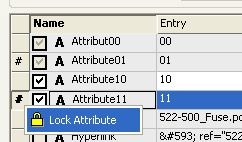
NoteThis command is only displayed with locked devices, if the Allow change of lock behavior option is checked (in DBE mode's Format -> Attribute Name...) for the corresponding attribute.
The attribute is locked and can no longer be edited. |
|
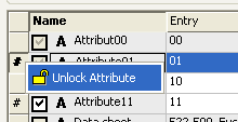
NoteThis command is only displayed with locked devices, if the Allow change of lock behavior option is checked (in DBE mode's Format -> Attribute Name...) for the corresponding attribute.
The attribute is unlocked and can be edited. |
|
|
Don't purge if device is used |
Additional devices, which are not placed in project, often need to be listed in Bills of Material.
To do so, the required components are loaded into the project without placing them on a sheet.
In such cases, however, the Purge unused objects command cannot be executed, as these required objects would be removed as well.
When the Don't purge if device is unused option is checked, the device (also applies to connectors, cables and blocks) is not deleted when executing the Purge unused objects command, even if no symbol is placed. Regarding assemblies, the option defined for the group gains higher priority. |
|
Device is master of assembly |
Check this option to define the selected device as master of the assembly.
This master definition is only valid for the devices of this assembly. Referencing via several nested assemblies is not possible.
NoteThis option is inactive with database assemblies.
|
|
Use structure from device |
It's possible to define the component assignment with taking over the device's structure. To do so, this option must be checked.
When assigning a component without structure to a device with "normal" component assignment, the checkbox can be used to control whether the component takes over the device's structure.
By default, the checkbox is activated and the structure is assigned to the component.
When a dynamic component without structure is already used in project, the checkbox is unchecked and inactive. If no component without structure is selected, the option is inactive.
Devices with dynamic symbols can be assigned to components without structure from the database. The checkbox is unchecked and inactive with those devices. |
|
Sealed |
If checked, the function 'Wire Seal' is used in combination with the connector pin terminal selection on the device.
NoteThe check box Sealed can also be predefined for components within the database editor (under Component Properties - Component). |
Variants/OptionsThis part of the dialog is only displayed if variants/options have been defined in the project and the Standard Mode is active. |
|
|
Variants to change for |
Selection of the variants you want to change in the dialog. Before making modifications, the desired variant has to be defined. |
|
Create new instance |
A new instance of the component is created for the variant. |
|
Set changes to default |
This button resets changes made to the set variant. |
To delete an attribute, right-click on the left (gray) column of the table, adjacent to the attribute to be deleted, and select the Delete Attributes... command from the displayed context menu.
Non-full-scale cable ducts
The system attribute .CABLE_DUCT_LENGTH may be used for defining a fixed, non-full-scale length for a cable duct. Existence of that attribute is shown graphically by means of two fracture lines ( ) on the cable duct.
Note
If 0 is entered as attribute value, the graphical length is used. The value 0 allows you to define the graphical length as one variant and a full-scale length as another variant.
Length of a wire is determined as follows:
-
If a non-full-scale length has been defined, it is applied.
-
If the wire is not laid in a cable duct with non-full-scale length, the graphical length of the wire is applied.
-
If a piece of the wire runs through a non-full-scale cable duct, the proportional distance within the cable duct is applied. This means, if a piece of wire runs only through half the cable duct, only half of the non-full-scale length is applied.
Exception
If the end point of a piece of wire is positioned nearby the cable duct end (difference < cable duct width), the cable duct end is taken as the base. As the end point of the wires lies in the center of the cable duct, the wire length would else depend on the type of cable duct connections.
Dimensioning: If a cable duct has a length dimensioning (both ends of the dimension are attached to the cable duct), the non-full-scale length of the cable duct is output as measured value.


