
Place Connectors
Placing and navigating between devices can easily be done by working in the Devices Tree View of the Project Window and the Component Tree View of the Database window.
Regarding the placement of any objects in the drawing, user- and project-specific settings can be defined in Tools -> Settings -> Placement.
To find more information on placing devices, symbols and subcircuits, please see also:
To place connectors
Use the Component Tree View of the Database Window or the Device Tree View of the Project Window, selected with the appropriate tab,
-
select the desired connector,
-
drag it to a sheet window (or right-click on the connector and use one of the Place commands from the displayed context menu),
-
release the mouse button and the connector will be placed in the drawing.
The following rules are adhered to:
-
Selection of the context-menu command Place (or a Drag&Drop operation) when a component or connector device has been selected will place the complete connector as a pin group, i.e. a single symbol representing all the connections.
-
Selection of the context-menu command Place Single Pins, when a component or connector device has been selected, will place the complete connector as individual pins, i.e. individual symbols representing each of the connections.
-
Selection of the context-menu command Place (or a Drag&Drop operation) when a single pin, of a component, or connector device, has been selected will place it as a single pin.
-
Selection of the context-menu command Place (or a Drag&Drop operation) when several pins are selected in the Tree View, will place symbols for each of the selected pins.
-
Selection of the context-menu command Place as Pin Group, when several pins are selected in the Tree View, will place a single symbol representing all of the selected pins.
Drag&Drop operations
Connectors/Block connectors
Connectors are combined into a pin group and placed as one symbol. When placing the pins from within the Database Window, a new connector is created, i.e. the complete connector is placed in the drawing and appears in the Device Tree View.
Pin(s)
If only one connector pin is selected, it will be placed as a single symbol. Both Tree Views also allow for the selection of several pins, of a connector, at one time. These will then be placed together, but as single-pin symbols.
Text is optimized (i.e. set as invisible) so as to get a representation without redundant displays of information associated with the pins. The Symbol Designation, if it exists, is not displayed at any symbol. The Pin Number is displayed at all symbols. The Device Designation is displayed at the first symbol and the Component Code at the last one.
Note
The text visibility for connector symbols can be defined under Tools -> Settings -> Placement -> Connector Symbols.
Commands in the context-menu
Place
This option provides the same functionality as a Drag&Drop operation on the desired object, however the result is different for connectors and their pins (see above)
If a E3.panel license is available, this option will place the panel symbol on the panel sheet.
Place one-by-one
This command places all pins of a connector one after the other.
If a E3.panel license is available, this option will place the panel symbol on the panel sheet.
Place Insert as Pin Group
Only available for connectors with inserts: This command places a symbol with all pins for each connector and insert contained in the selected connector/insert.
Place Complete Device
Only available for connectors with inserts: This command places a symbol with all pins contained in the selected connector/insert.
Place Pin Group
This option is only available if several individual pins are selected. It allows you to place specific pins together as one symbol, i.e. as a pin group.
Place Single Pins
This option is only available in conjunction with connector components that have several pins that can be placed. The pins are not combined together as a pin group, but placed as single-pin symbols. A complete connector can, for example, be placed in the form of single pins without having to display and select the pins individually in the Tree View.
If a E3.panel license is available, this option will place the panel symbol on the panel sheet.
Place Master Symbol
This command places the connector's master symbol on the sheet.
Place as Graphic
This option will break down the symbol in graphics and place them on the sheet.
When placing connectors, please bear in mind the following:
-
When placed as a block connector, the pin symbols are automatically aligned on the edge of the block. Moving from one edge of the block to another, during placement, will automatically change the orientation of the pins.
-
A connector cannot be placed as a block connector if no block-connector symbol has been defined for it in the database. In this case the user will be informed by means of an error message No block connector defined in database! during placement.
-
Meaning of the different cursor symbols during placement of block connectors:
-
When a block connector (or its pins) is dragged from within the Device View of the Project Window or the Component View of the Database, and moved across the edge of a block, the cursor changes shape to indicate that placement would be possible, indicated by a small block symbol adjacent to the cursor.
-
When you try to place the block connectors outside an appropriate block, the cursor symbol indicates that the position is invalid.
-
Additional information regarding invalid positions is displayed in red color in the Status line.
-
-
If a pin of an existing connector is selected from within the Device Tree View for placement,
-
it can only be positioned outside of a block, if the existing pins are already placed outside a block, i.e. as a free connector, or
-
it can only be placed on a block if the existing pins are already placed on a block
- or if none of the remaining pins of the connector has already been placed
-
-
Normal connectors can be placed inside a block by pressing the Shift key while moving them onto the block.
-
The desired block, to place block connectors on, can easily be located by means of the Jump function, i.e. double-click on the block in the Device Tree View and select Jump from the displayed context menu.
-
Plugging connections
This functionality is only available, if a E3.panel license is present!
Connector symbols in Schematic can be plugged in. This is accomplished through placement on 'Point Slots'; this means, a 'point slot' with appropriate mounting method is defined on the model of the connector. The mating connector is assigned the same mounting method. This allows to put together the connectors on placement.
If both the connector and its mating connector are assigned a 'Point Slot', it is irrelevant if the connector is plugged into the socket or the socket into the connector. Both methods are possible.
Note:
Connectors that are connected that way in the panel, are not connected in the schematic. This means, signals, ... are not transferred.
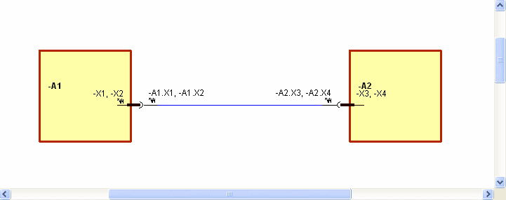
Simultaneously Place Connector and Mating Connector in Connection
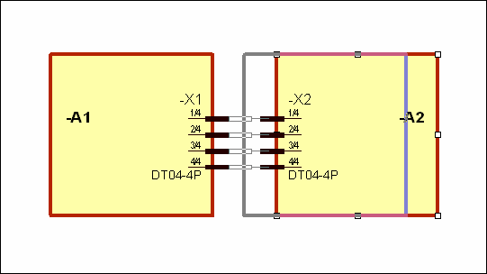
Disconnecting points are often inserted belatedly in a cable harness. Such a disconnecting point (a so-called inliner) is a plug connection between two individual cable sets. Example: instrument panel.
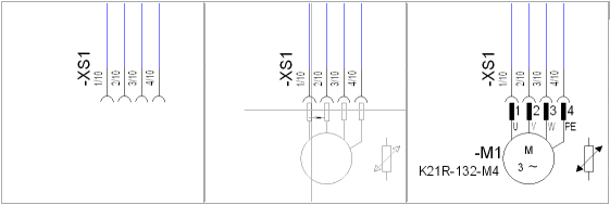
When inserting a connector into a connection in E3.cable, the connection is disconnected and the connector is placed on one side. The other side of the connection remains open. The defined mating connector is also placed.
It is possible to place a connector with mating connector definition into a connection. The corresponding defined mating connector is generated and placed as plug connector. E3.cable's operation is the same when placing from within the Database tree or the Project tree.
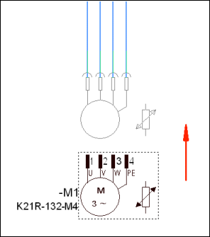
This is now also valid for non-connector components with mating connector definition. The figure shows how a motor with mating connector is moved to open connect line ends. Mating connectors are generated according to the database definition.
To place symbols on connectors
'Normal' symbols can be connected to a connector when placing from within the Device or Database tree.
Example
To place block connector symbols on blocks
Similar to free connectors or connector symbols, block connector symbols can be dragged from the Symbol Tree view and dropped onto blocks. The difference is that block connector symbols can only be placed on blocks.
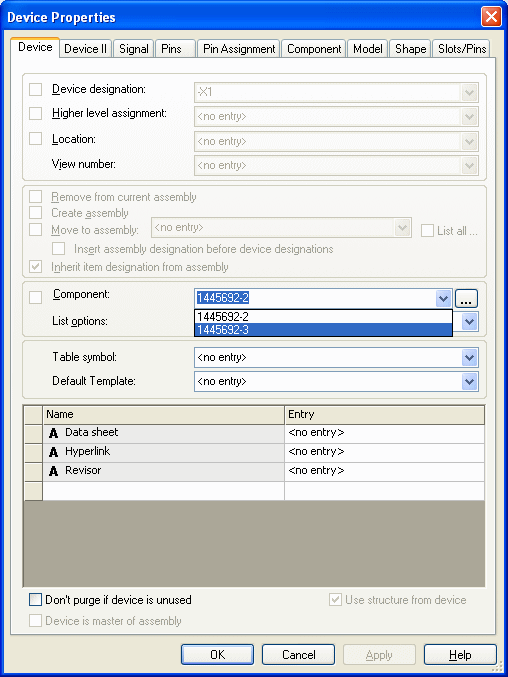
Optionally the component code of an existing block connector can be modified or removed by selecting <no entry> in the Device Properties dialog. By doing this, a component is no longer assigned the device and the Component field is empty.
Independent block connector symbols, that have been placed, and are not part of a component, can be assigned to a component by selecting a component from the drop down list on the Device Properties dialog (similar to free connector symbols).
Note
In order to assign the connector symbol to a component, the symbol must first be assigned a Device Designation.
When the block connector symbol(s) is assigned to a component, the view number of the block and the number of pins placed on the block are checked. For example, if a connector symbol is placed on a block view, the appropriate view number is assigned to the connector view. Also, if several connector pins are placed, the remaining (unplaced) pins, of the Connector component, are displayed in the Device Tree view ready for placement.
Block connectors on different blocks can have the same connector designation. This enables, for example, a connector to be placed on two blocks with the connector having the same Device Designation -X1 on both blocks. To do so, check the Allow same connector designations on different devices option in the Settings.
Plugging One Block Connector on Another
Plug-in mounts between block connectors and normal symbols can be generated by moving the normal symbols. Furthermore, plug-ins can be generated and disconnected by moving block connector symbols along the block's outline. By moving a block or a normal symbol, the plug-in connections to the block connectors are disconnected.
When changing the block size, the affected block connectors are plugged;the affected block connectors are unplugged when they are not plugged on a free connector.
To place connector master symbols /documentation graphics
For documentation purposes, it is possible to add a special representation of a connector to the layout:
-
connector master symbol
>>> complex representation containing logic information
-
documentation graphic
>>> simple graphical representation without logic information
The connector master symbol/documentation graphic can be defined in the Database for connectors. When the component is selected from the database, this symbol is displayed in the Preview Window.
The connector master symbol can be placed in the drawing only once. A documentation graphic can be placed as often as required in the drawing.
To place a connector master symbol
-
right-click on the desired connector in the Device tree view of the Project Window and select the Place Master Symbol command from the displayed context menu.
To place a documentation graphic,
-
right-click on the desired connector in the Device tree view of the Project window and select the Place Documentation Graphic command from the displayed context menu, or
-
right-click on the desired connector in the drawing and select the Place Documentation Graphic command from the displayed context menu.
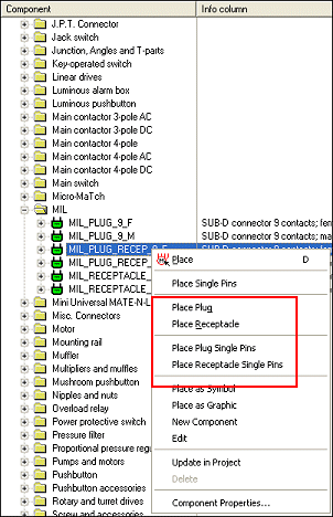
To place MIL-Standard connectors
Connectors containing of MIL Standard symbols only can directly be placed as MIL Standard connectors from within the Database tree:
-
Place plug / Place receptacle
These commands are displayed on connector components containing MIL symbols.
-
Place plug single pins / Place receptacle single pins
These commands are displayed on connector components containing receptacle MIL symbols.
-
"Drag&Drop" on a connector component in the Database window places the default symbol.
-
When not all required symbols with characteristics are generated, only the normal connector can be placed.
-
When placing the single pins doesn't generate a continuous line, graphic lines are drawn to group the pin symbols.
Special settings can be defined in Settings -> MIL-Standard.
-
Using the context menu commands Place plug / Place receptacle, a connector's view can easily be switched between Receptacle and Plug, provided that both views are defined for the connector. See also: MIL-Standard
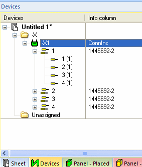
Placing connectors with inserts and selecting the desired connector pin terminal
After having defined a connector with inserts in the database, the corresponding and desired connector pin terminals can be defined and selected in the project.
Select the desired connector with insert in the Database window's Component tree and
-
either drag the connector with inserts into the Project window's Device tree, or
-
drag the connector with inserts into the workspace.
The active connector pin terminal of the connector with inserts can then be defined in two ways:
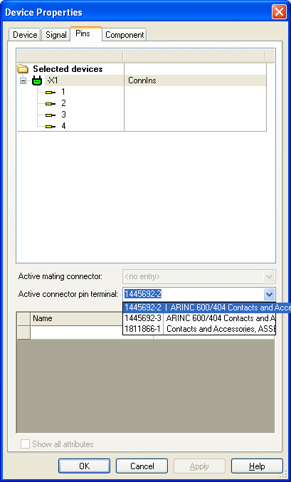
1st Possibility
-
right-click on the connector with inserts in the Device tree,
-
select the Device Properties command from the displayed context menu,
-
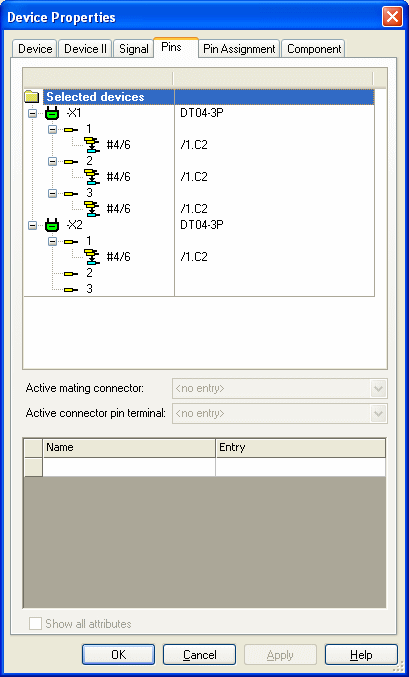
switch to the Pins tab in the Device Properties dialog box,
-
select the connector, if the connector pin terminal is to be valid for all cavities. Select the desired cavity, if the connector pin terminal is to be valid for the individual cavity.
-
Click on the drop-down list under Active connector pin terminal to select the desired connector pin terminal.
2nd Possibility
-
right-click on the connector insert in the Device Tree,
-
select the Device Properties command from the displayed context menu,
-
switch to the Device tab in the Device Properties dialog box,
-
click on the drop-down list under Component: and select the desired connector pin terminal.
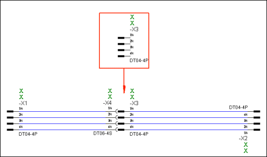
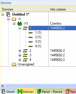
Displaying several connectors in one symbol - Pin Groups
Usage and Creation in Project
For simplified display of connectors, it's possible to display pins of different devices in one symbol. Such a group is possible for individual connectors and also for several connector pins. Therefore, a special pin group is available similar to 'pin views'. What is more, pin groups can be used for hierarchical blocks to simplify the hierarchical display.
These groups exist besides the 'normal' display and can be generated as often as desired.
To generate a pin group it's not necessary to do any enhancements to database symbols or components.
A pin group can be generated by using Drag&Drop from within the Device or Database tree view, or, when the connector is already placed, using the Merge to an existing connector symbol option in the Split or merge connector pins dialog.
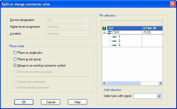
After closing the dialog with this option activated or after Drag&Drop from the tree view, the connector appears at the cursor and can be dragged to the desired connector, that should be merged to the group.
With the Split or merge connector pins dialog, already placed pins can be moved or deleted using the Remove pins from pin group option. The corresponding pins must therefore be selected in the Pin selection section.
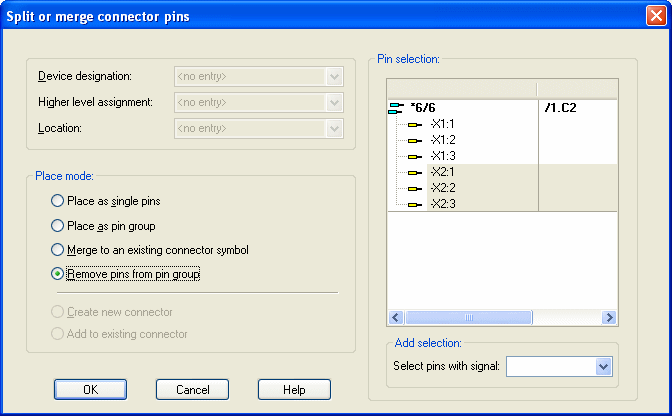
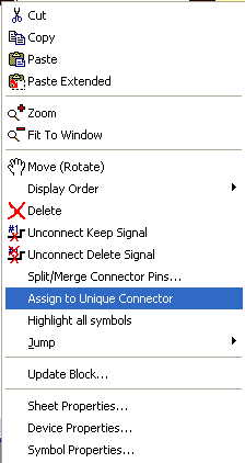
It is thus possible that pin groups can exist of pins of only one single connector. In this case it's possible to convert these to the original connector view using the Assign to Unique connector command from the connector's context menu.
The following should be considered when creating pin groups:
-
Pins must not be contained twice.
-
Pins must be from the same view.
-
The pin group must not be plugged. When connectors are plugged, the functionality is restricted.
Display and Navigation in Device Tree and Project
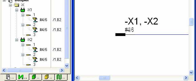
After having created the pin group, the original symbol is kept regarding the symbol display. The pin belonging to a pin group, is represented by the corresponding icon in the Project tree view: ![]() .
.
Navigation within Device tree / drawing:
-
Double-clicking on a pin of a pin group jumps from the Project tree into the drawing. This functionality is also available with the Jump -> Jump to Schematic command from the context menu.
-
It's also possible to jump from the connector to the tree structure using Jump -> Jump to Tree.
-
Jump -> Jump to Device Table from the context menu of the Device tree or the placed connector on the sheet jumps to the corresponding connector in the Device table.
Modifying Pin Group Properties
The group is dynamically structured so that changes to assignment and to the connector can be realized any time.
All pins contained in a pin group are handled like a multi-selection in the Device Properties. In addition, the selection of a symbol of a pin group in the trees of the Signal and Pins tabs is like in the Device tree.
This display, however, is valid only with pins that are affected from the symbol selection. I.e. the display must not necessarily correspond to the display in the Device tree.
In the Symbol Properties -> Symbol tab, it's not possible to assign to a device. Only graphic information can be changed. In the Symbol Properties -> Signal tab, the pins of the pin group are just listed.
Text Types for Pin Groups
The following text types are evaluated for pin groups and output in a list. The list entries are separated by comma and contain information on the individual connectors:
-
#12 Device Designation
-
#15 Location
-
#14 Higher Level Assignment
-
#1010 Device name
These text types are subject to the shortening rules (e.g. with fields).
In addition, two more text types are displayed as follows:
-
#203 Connector pin name
-
#213 Connector pin name / total
[#|*][Number of connector pins contained] [/] [Number of all connector pins]

Example with the connectors -X1, -X2 and -X3 containing 3 pins each:
-
Each pin '1' is part of a pin group -> #3/9
-
All pins except '3' are part of a pin group -> #6/9
-
All pins are part of a pin group -> *9/9