
Placement - Symbols
|
Symbols |
|
|---|---|
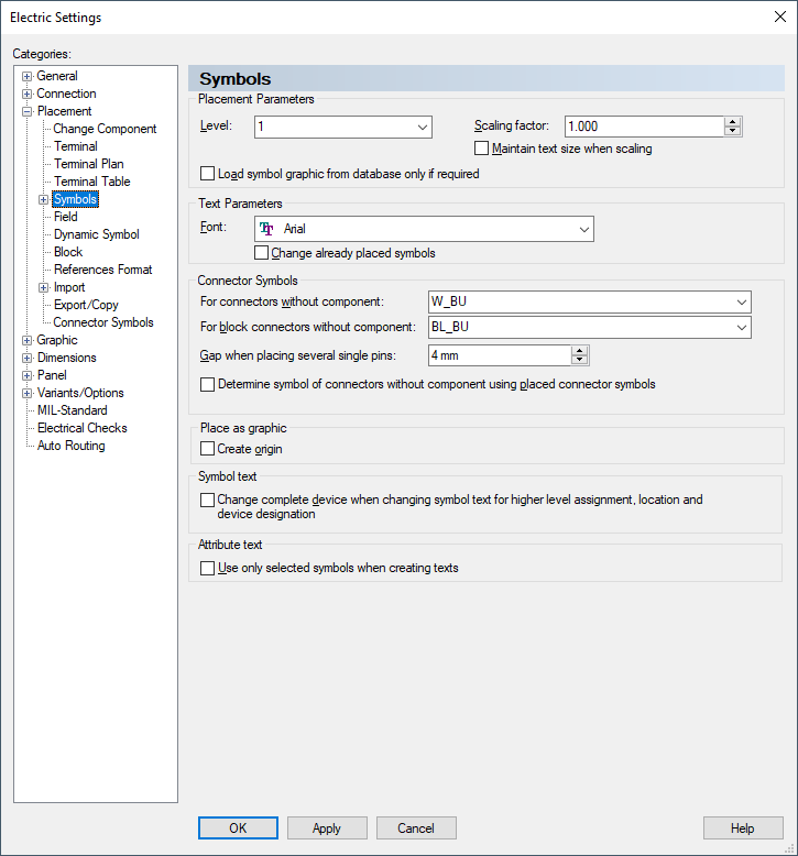
Placement Parameters |
|
|
Level |
Defines the level on which the symbol is placed.
Changes made to the settings apply only to symbols that are placed after the change, not to already placed symbols. |
|
Scaling factor |
A scale factor can be used to place symbols at a different size to the original.
With the standard installation, the Scaling Factor button is not included on the standard toolbars. It can be added from the Place category in the Tools -> Customize - Commands dialog.
When the symbols are placed, the associated symbol text is also scaled. To prevent scaling of the text, check the below 'Maintain text size when scaling' option.
By default, the Scaling factor is set to 1.0. Values between 0.1 and 100.0 are allowed. |
|
Maintain text size when scaling |
This option prevents scaling of the symbol text - see above. |
|
Load symbol graphic from database only if required |
By default, the option is inactive, i.e. the symbol graphic is always loaded. When loading a component, all symbols in the structure are loaded (for connectors the documentation graphics as well).
Likewise, all mating connectors and their symbols are loaded. Because different mating connector components can be defined for these, it's possible that a large amount of database information, which is not presently required or possibly never needed, will be loaded when calling up a component.
Check this option to load the symbol graphic only when required (for example when placing or in the Preview window). |
Text Parameters |
|
|
Font |
Defines the font used for symbol text.
Changes always apply to the fixed symbol text (so-called internal symbol text) of already placed symbols. |
|
Change already placed symbols |
When Change already placed symbols is checked, all symbol texts of already placed symbols are changed.
When unchecked, the new font applies only to symbols that are placed after the change. |
Connector Symbols |
|
|
For connectors without component |
Defines the default symbol for normal connectors.
It will be used for the placement of connectors, if the connector doesn't belong to a component and no pin of the connector has been placed.
The selection list displays all valid symbol names available in the database. |
|
For block connectors without component |
Defines the default symbol for block connectors.
It will be used for the placement of block connectors, if the block connector doesn't belong to a component and no pin of the block connector has been placed.
The selection list displays all valid symbol names available in the database. |
|
Gap when placing several single pins: |
If several connector symbols are placed simultaneously in the form of individual pins, for example with the commands
they are arranged vertically using the defined spacing.
The up-down arrows allow you to change the value in steps of 1mm.
It is recommended that this value is set to a multiple of the working grid in order to enable an easy connection of the symbols upon placement. |
|
Determine symbol of connectors without component using placed connector symbols |
When this option is checked, E3.series determines the symbol for a pin / pin group from already placed symbols of the corresponding connectors without component name.
When this option is unchecked, the symbol of the corresponding component is used in case a mating connector is defined, otherwise the default symbols for connectors are used (see above). |
Place as Graphic |
|
|
Create origin |
Defines a zero point symbol automatically generated when placing a symbol as graphic. |
Symbol text |
|
|
Change complete device when changing symbol text for higher level assignment, location and device designation |
When this option is checked, the device's item designation is changed when editing/changing the symbol text (i.e. Higher level assignment, Location and Device designation) in the Text Properties or using F2.
When changing the symbol text in the Symbol Properties, this option is not considered.
NoteWhen selecting the command Place as graphic for the symbol in the tree and the graphic is placed on the sheet, a new unplaced device is generated in the tree. |
Attribute text |
|
|
Use only selected symbols when creating texts |
When this option is checked, attribute texts (text type # 1000) are displayed only on the symbols that have the corresponding text types assigned in their Device Properties.
Texts that are already visible in the project are not hidden by this option. Superfluous texts must be deleted manually. |