Defining Models
To define a model, start the Database Editor.
There are two possibilities to create a model:
-
The easiest way of creating a new model is to base it on an existing one and modify it. To do so, select the New command from the context menu of an already existing model, displayed by right-clicking on a model in the Model or Component tree view of the Database Window, or by right-clicking on the column header with an existing model highlighted. This method will create a new model based on the selected model.
-
To create a completely new model, with no model highlighted, select the New Model command from the context menu displayed by right-clicking on one of the headers of the Database Window. This method is used to create a new model from the scratch.
Creating a new model
Select the New Model command from the context menu displayed by right-clicking on one of the headers of the Database Window.
A new working area (drawing sheet) named Model NewModel# is created. Its size depends on the size defined in the Tools -> Settings -> Database Editor -> Model dialog box.
The grid display can be activated using View -> Rulers and/or Grid and modified using Tools -> Settings -> Database Editor -> Model.
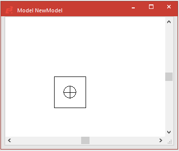
To start creation of the new model now, proceed as follows:
Model name, type and description
-
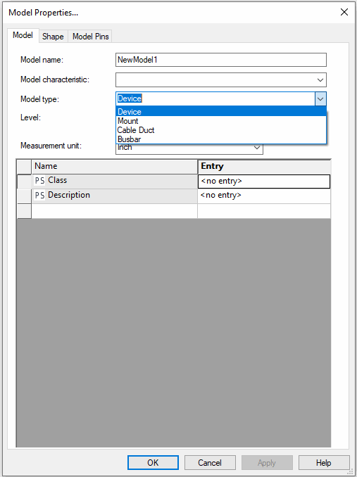
Establish the model's name, its type and description: in the working area's context menu, activate the Model Propertiesdialog box and assign the model a name (52 characters), define its type and additional attributes.
Origin
-
The physical zeropoint of the new model is placed in the middle of the working area. The Symbol Origin toolbar button
 is used for moving the model origin to another position. The Z-coordinate is always 0.
Graphics
-
Create the model graphics to define how you want the model to look when placed inside the panel,
-
by using the graphic draw commands on the Graphic Toolbar (line width, color, level and style).

Example
-
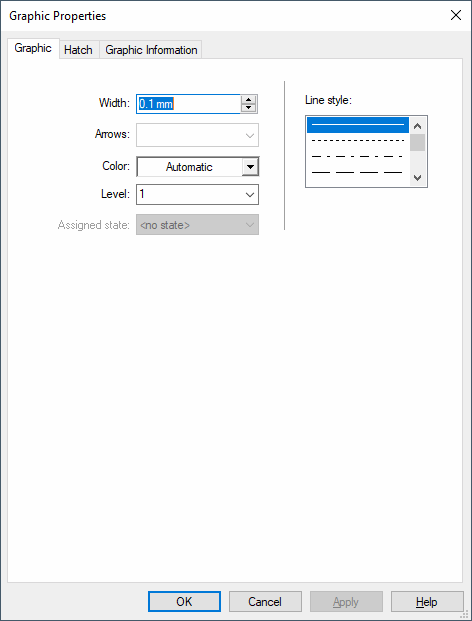
Or by using the Graphic Properties... from the context menu of the selected element;
-
-
by placing existing symbols or models from the tree view of the Database Window;
-
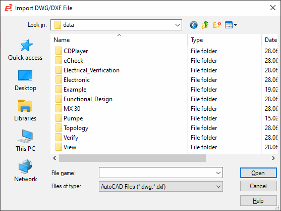
by importing a DXF/DWG file of the required model.
-
All graphic objects (except for model graphics that represent the space requirements) can be sent to the back or brought to the front. This makes it easier to add a fill effect to the objects. The following functions are available both in the graphics context menu (Display order) and as toolbar buttons: Bring to Foreground, Send to Background, Bring forward, Send backward.
Note
Model graphics in DBE are an exception which represent the physical place requirement. These always have to be placed on the hindmost level system-generated and can thus not be moved.

Model shape
-
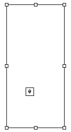
The initial model shape / model's space requirement is depicted by a square located around the original origin location. To define the model shape click on the model type in the NewModel#' tree view, to highlight the shape. Then adjust the shape to suit the model graphics by moving the shape handles. Alternatively, click on the Fit Space Requirement button
 . To define a polygon, right-click on the selected model and select the Edit points command from the displayed context menu. Then right-click where another corner point for the polygon is to be added and select Add Point.
Example

Pins
-
Define the pins:
-
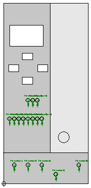
Select and place the pre-defined connection symbols, so-called Node Templates, from the Database Symbol Node Toolbar, by first selecting the required symbol from the drop-down list and then by selecting the Single node button
 (e.g. Node - all directions). (Double-clicking on the pin will allow multiple placement of pins of that type). During placement of the symbol, the system displays both the connect direction and a box symbolizing the text nodes.
Example
-
-
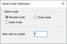
Define the pin order by using the Node Order button
 (or select the command Edit -> Order Definition -> Node).
-
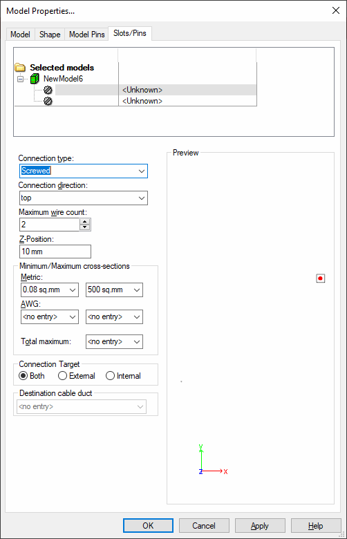
The properties of the pins can be modified in the Slots/Pins tab of the Model Properties.
Text Types
-
Place user-defined text nodes:
-
This is done by selecting the Text button
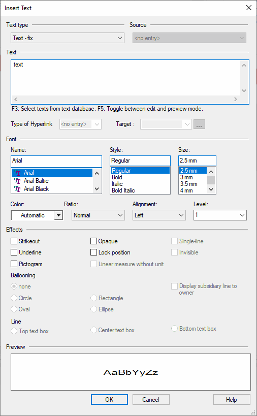
 on the 'Database Symbol Text' toolbar, which displays the Insert Text dialog box. The text node can be selected from the Text type Drop-Down menu. For Device Designations, Component Codes, Symbol Designations, etc., the Text field is left empty, whereas, for Symbol Texts, Sheet Texts, etc., a value may be entered. Once placed, the text node can be changed as required by simply clicking on it and selecting a new text type from the Symbol Text Drop-Down list on the Database Symbol Text toolbar
  . The text type Pin Name must be connected to a pin (context menu Group).
-
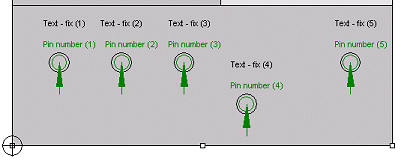
The display mode of the pin names can be toggled between a node #, a description and a simple location marker (an 'X') by selecting the Num, Typ or Text button on the Database SymbolText toolbar (represented as '#3', as 'Pin Number' or as 'X').

Example
-
-
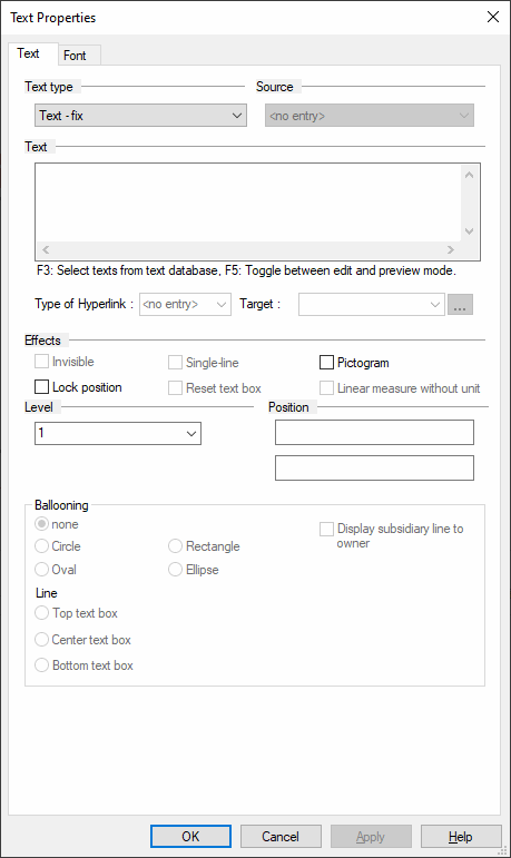
An existing model text can be changed by first selecting it on the sheet and then completing the desired changes in the corresponding toolbars or in the Text Properties... directly.
Restricted Areas, Drill Holes, Cutout Areas
-
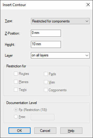
Add restrictions to the model to prevent certain elements from being placed on the area defined or add drill holes or cutout areas to allow placement of certain elements within defined areas.
-
by using the Contour... command on the Insert Main menu (or the Insert Contour button
 on the Database Model toolbar);
Example
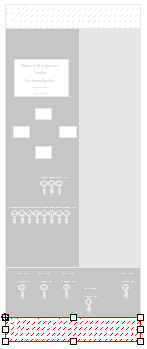
Note
A model can be placed on several cutout areas lying one upon the other, as long as there is no self-intersection (see red circle).

-
Physical Description: height, pin description, mounting position
-
Adding the physical description:
-
Establishing the mounting types (Shape tab of the Model Properties dialog box)

-
Defining the component's height (Shape tab of the Model Properties dialog box)
-
Defining the placement position on the mounting (Shape tab of the Model Properties dialog box)
-
Physical description of the pins (Slots/Pins tab of the Model Properties dialog box)
-
Slots
-
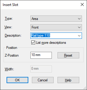
Insert slots to define how and what device can be mounted on the device
-
by using the Slot... command on the Insert Main menu (or the Insert Slot button
 on the Database Model toolbar)
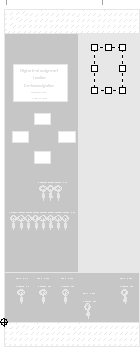
Example
Note
Define the point of view from which the slot is to be placed in View. The predefined X-/Y-/Z-Position specifies the slot for the outside. To define a slot for the model's inside, use View to select the direction from which the slot is to be mounted to the model. Position defines the distance in which the slot is to be placed depending on the selected view. In this way slots can be defined for each of the model's sides.
-
-
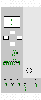
Finally, the new model can be saved to the database by means of the Save to Database command from the object menu. All coordinates of the model's objects are saved in the database as relative to the model zeropoint. This is what the new model looks now looks like:
-
Assigning the model to a component (in DBE mode when creating/editing a component):
-
This is done using the Pin/Conductor Assignment ->Schema/Model command on the Edit Main menu (or the Pin Assignment Symbol/Model button
 on the Database Component toolbar)
In the component definition, the desired model will be placed in the working area and the circuit diagram's pins will be assigned to the model's corresponding pins (or vice versa).
-