
Model Properties - Shape
With Database Editor mode disabled, only few modifications can be made.
To display the properties of a model (in Project mode),
-
right-click on the model in the Project window's tree view (Panel - Placed or Panel - Unplaced) and select the Model Properties... command from the displayed context menu and select the Shape tab.
Note
The Model Properties are only available in the context menu of the Project window's Panel trees (Placed and Unplaced) and when the Devices option is checked in the Tree Control Properties - General dialog for the Panel trees.
To display/modify the properties (in Database Editor mode),
-
right-click on the model in the Model Tree of the Database Window and select Model Properties... from the displayed context menu and select the Shape tab.
In this case no modifications can be made. The dialog only serves for information on the different database entries.
-
To modify the properties, right-click on a model in the Model Tree of the Database Window, select New or Edit from the context menu and select the Model Properties... command from the displayed context menu activated on the model itself in the working area and select the Shape tab,
-
or select the Properties... command from the context menu activated on a model in the DBE's Project Window tree view and select the Shape tab.
A dialog box appears in which you can display/modify the properties (its contents depend on the object selected):
|
Shape |
|
|---|---|
|
Mounting Description |
Displays a list of all the defined mounting rails for the component.
The component can only be placed on a corresponding mount rail or on slots of other components that have one of the defined mounting types. |
|
Available descriptions |
The drop-down list displays all mounting types used in the project.
If the checkbox 'List more descriptions' has been checked, all mounting types available in the database are listed or a new mounting type can be entered directly into the input field. |
|
List more descriptions |
Activate this checkbox to display all mounting types defined in the database. |
|
Add |
Adds the mounting type selected (or entered directly) in the Available descriptions drop-down list to the list displayed in the Mounting Description window. |
|
Delete |
The Delete option removes the selected mounting type from the model. |
|
Position (X/Y/Z) |
If the component has already been placed in a panel, its location is displayed in the 'Position' fields.
In Database Editor mode, the position fields are empty. The position of the component cannot be modified in the dialog box. |
|
Size (X/Y/Z) |
The size can only be modified in Database Editor mode.
|
|
Changeable |
Check this option to create dynamic models (similar to dynamic symbols).
This makes sense, for example for mounting plates that are manufactured dynamically according to their size and thus not every size can be predefined in the database.
This option can only be activated if the outline's graphic (i.e. the polygonal lines that define the space requirement) displays a rectangle. If this option is active, the space requirement cannot be changed from a rectangle into a polygon.
Concerning models on panel sheets having this option checked, the size (i.e. length, width and height) can be changed in the Project mode's Device Properties -> Shape dialog.
Exception: Components of model type 'Mounting rail' or 'Cable duct'. These can only be modified in their length (X direction).
This checkbox defines, whether the mount or cable duct has
in the project. |
Justification forThe justification can be modified in Project mode as well as in Database Editor mode.
Note
The justification can be changed in Project mode only if the device itself as well as the objects placed upon are not locked. |
|
|
Slot points X/Y/Z |
The following is valid for 'point' slot types (e.g. when one component is plugged on another):
A negative value for X means that the component is displaced on the X axis to the right. And a positive value, means that the component is displaced on the X axis to the left.
A negative value for Y means that the component is displaced on the Y axis to the top. And a positive value, means that the component is displaced on the Y axis to the bottom (down).
A negative value for Z means that the component is placed on the Z axis to the front (raised). And a positive value, means that the component is placed on the Z axis to the back (sunken). |
|
Slot lines Y / Z |
The following is valid for 'line' slot types (e.g. placement on mounting rail):
A negative value for Y means that the component is displaced on the Y axis to the top. And a positive value, means that the component is displaced on the Y axis to the bottom (down).
A negative value for Z means that the component is placed on the Z axis to the front (raised). And a positive value, means that the component is placed on the Z axis to the back (sunken). |
|
Slot areas Z |
The following is valid for 'area' slot types:
A negative value for Z means that the component is placed on the Z axis to the front (raised). And a positive value, means that the component is placed on the Z axis to the back (sunken). |
|
Reset |
This button resets the justification to the values defined in the database for the current version of the model.
The button is only active, if the current values differ from those defined in the database and if the position is not locked. |
|
Layer |
This functionality is only relevant for models, which are converted to CADSTAR using the 'E32CADSTAR' converter.
In this drop-down list the space requirement for the placement side of the model can be defined.
The following layer possibilities are available:
|
|
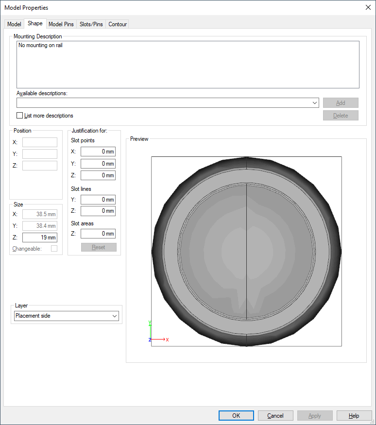
Preview |
Displays a schematic, three-dimensional image (top view) of the component.
The depth is shown as (relative) proportional value.
The size of dynamic components (for example length of mounting rails or cable ducts) can be modified in Project mode.
For non-dynamic components, only the depth can be modified in Database Editor mode. |