Device Properties - Shape
The Shape tab is only displayed when a device, with a model definition, is selected.
With Database Editor mode disabled, only few modifications can be made.
To display the properties of a model in Project mode:
-
With the required device selected in the Drawing Window, select Format->Device Properties from the Main Menu bar and select the Shape tab, or
-
right-click on a device on the drawing and select the Device Properties... command from the displayed context menu and select the Shape View or
-
right-click on a device in the Project Window's tree view and select Device Properties... from the displayed context menu to display the Device Properties dialog box, and select the Shape tab.
The following dialog box is displayed:
|
Shape |
|
|---|---|
|
Mounting Description |
Displays a list of all the defined mounting rails for the component.
The component can only be placed on a corresponding mount rail or on slots of other components that have one of the defined mounting types. |
|
Available descriptions |
The drop-down list displays all mounting types used in the project.
If the checkbox 'List more descriptions' has been checked, all mounting types available in the database are listed or a new mounting type can be entered directly into the input field. |
|
List more descriptions |
Activate this checkbox to display all mounting types defined in the database. |
|
Add |
Adds the mounting type selected (or entered directly) in the Available descriptions drop-down list to the list displayed in the Mounting Description window. |
|
Delete |
Removes the selected mounting type from the list displayed in the Mounting Description window. |
|
Position (X / Y / Z) |
If the component has already been placed in a panel, its location is displayed in the 'Position' fields.
In Database Editor mode, the position fields are empty. The position of the component cannot be modified in the dialog box. |
|
This checkbox is only active, if the device has not yet been placed but exists in the Panel - Unplaced tab of the project.
Check this option to place the device at a freely definable position.
NoteFor already placed devices the free placement functionality can be executed later. While moving, press the hotkey P to call up the dialog Input Coordinates. |
|
|
Lock position |
This checkbox is only available when Device Properties is selected in Project mode for a device that has already been placed in a panel.
Check this option to prevent the panel device being moved in error (Move command or Drag&Drop operations). It will still be possible to cut (CTRL+X) and paste the device to another position.
NoteTo move locked objects, press the F key in the schematic while moving and the F key in the panel before moving, to still move objects with locked position. |
|
Size (X / Y / Z) |
The size can only be modified in Database Editor mode.
X describes the width of a component or the length of a mounting rail or cable duct. Y describes the height of a component or the width of a mounting rail or cable duct. Z describes the depth of a component, mounting rail or cable duct. |
|
Changeable |
Concerning models on panel sheets having this option checked, the size (i.e. length, width and height) can be changed in this dialog.
ExceptionComponents of model type 'Mounting rail' or 'Cable duct'. These can only be modified in their length (X direction).
In addition, this checkbox specifies, whether the cable duct or mounting rail has
in the project.
This option can be activated in the Model Properties - Shape dialog box. |
Justification forThe justification can be modified in Project mode as well as in Database Editor mode.
NoteThe justification can be changed in Project mode only if the device itself as well as the objects placed upon are not locked. |
|
|
Slot points X / Y / Z |
The following is valid for 'point' slot types (e.g. when one component is plugged on another):
A negative value for X means that the component is displaced on the X axis to the right. And a positive value means that the component is displaced on the X axis to the left.
A negative value for Y means that the component is displaced on the Y axis to the top. And a positive value means that the component is displaced on the Y axis to the bottom (down).
A negative value for Z means that the component is placed on the Z axis to the front (raised). And a positive value means that the component is placed on the Z axis to the back (sunken). |
|
Slot lines Y / Z |
The following is valid for 'line' slot types (e.g. placement on mounting rail):
A negative value for Y means that the component is displaced on the Y axis to the top. And a positive value means that the component is displaced on the Y axis to the bottom (down).
A negative value for Z means that the component is placed on the Z axis to the front (raised). And a positive value means that the component is placed on the Z axis to the back (sunken). |
|
Slot areas Z |
The following is valid for 'area' slot types:
A negative value for Z means that the component is placed on the Z axis to the front (raised). And a positive value means that the component is placed on the Z axis to the back (sunken). |
|
Reset |
This button resets the justification to the values defined in the database for the current version of the model.
The button is only active, if the current values differ from those defined in the database and if the position is not locked. |
|
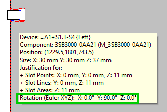
Rotation (Euler XYZ) |
Displays the model's rotation around the X, Y and Z axis.
The values are also displayed in the placed model's tooltip:
NoteThe tooltip is displayed only if the model contains at least one rotation value not equal to 0°. |
|
Unmeasured Length |
This option is only available, if a cable duct was selected.
Defines the unmeasured length of a cable duct.
The length can also be defined in the Device Properties' Device tab using the attribute .CABLE_DUCT_LENGTH.
The attribute will be displayed graphically with two break lines on the cable duct.
See also: Unmeasured Length |
|
Distance between cable duct inlet and outlet |
This option is only displayed if the Device Properties are activated on a Cable duct inlet/outlet.
Using Distance between cable duct inlet and outlet, a length can be defined for the virtual connection of the cable duct inlet/outlet
NoteThe distance between the cable duct inlet/outlet is graphically defined at the beginning of the arrow symbols:
|
|
Preview |
Displays a schematic, three-dimensional image (top view) of the component.
The depth is shown as a (relative) proportional value.
The size of dynamic components (for example length of mounting rails or cable ducts) can be modified in Project mode.
For non-dynamic components, only the depth can be modified in Database Editor mode. |
Variants/OptionsThis part of the dialog is only displayed if variants/options have been defined in the project and the Standard Mode is active, but is inactive with this tab. |
|