
Tree Control Properties - General
To display/modify tree control properties,
-
right-click anywhere in the Project window's tree (Sheet tab, Device, Panel-Placed tab, Panel-Unplaced tab...) and select the Tree Control Properties... command from the displayed context menu and select the General tab.
The Tree Control Properties dialog appears:
|
General |
|
|---|---|
|
Name |
Enter a new tree's name or modify the name of an existing tree. Select the
A dialog appears containing one row for each user interface language existing under the Language column. The second column is used to define the Name for the corresponding language:
|
|
Other Icon... |
Defines the icon, which is displayed in the tree's tab. The icon can be selected from the existing icons of the EXE file or from any DLL or EXE file. Clicking on the button opens the Change Icon file:
|
Show these objects |
|
|
Object |
The following objects can be defined or displayed:
|
|
Devices |
Display devices. The Info Column's selection list contains the following:
|
|
Symbols |
Display symbols. Placement defines, whether to display
The Info Column's selection list contains the following:
|
|
Pins (Devices) |
Display pins. The Info Column's selection list contains the following:
NoteConductor/ wire attributes can also be selected as pins. These are then correspondingly displayed in the info column of conductors/wires. |
|
Models |
Display models. Placement defines, whether to display
The Info Column's selection list contains the following:
|
|
Pins (Models) |
Display pins. The Info Column's selection list contains the following:
|
|
Slots |
Display slots. The Info Column's selection list contains the following:
Slots are listed below the view for which they are created.
The different slot types Point, Line and Area are represented by the following icons:
To directly jump to the sheet and highlight a slot, double-click on the desired slot of a placed model.
To display a slot's properties in the dialog Model Properties, select the command Model Properties... in the slot's context menu.
NoteSlot names can be changed in Database Editor. |
|
Contours |
Display contours. It's possible to display
|
|
Functional Objects |
-- This option is only available, when a E3.FunctionalDesignor E3.topology licencse is present! --
Display functional objects (such as functional units, ports, installation spaces etc.). Functional units and their ports are always displayed below their corresponding functional block or installation space.
See also: Functional Design / Topology |
|
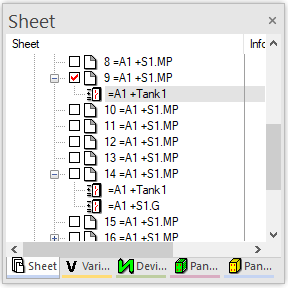
Sheets |
Display sheets. The Info Column's selection list contains the following:
|
|
Fields |
Displays the fields placed in the project and the structure node to which they belong. The fields can be moved by Drag&Drop into other structure nodes.
NoteIf a field belongs to the same structure node as a sheet on which the field is placed, the field is displayed only below the corresponding sheet. What is more, fields can be displayed within a sheet.
The Sheet tree view can thus show the sheets that contain fields and the structure node to which the fields belong:
|
|
Placement |
Defines the objects to be displayed: All, Unplaced or Placed objects. |
|
Info column |
Defines what is displayed in the Project window's info column. The drop-down list contains all attributes available in the database. |
|
|
Pressing the
NoteIndividual info columns are available for the individual objects.
AvailableAll attributes possible for the corresponding object are listed. Pressing the arrow button
NoteAttributes, which may appear on the same object repeatedly, can also be assigned repeatedly.
(So that an attribute can be assigned repeatedly to an object, the check box Single instance must be deactivated for the corresponding attribute in Database Editor Mode under Format -> Attribute Names....)
DisplayedLists the attributes used: Pressing the arrow button Pressing the arrow button Pressing the arrow button
|
|
Show View(s) |
This option defines, whether
Example:
All views available in project are displayed.
Only the original and first views are displayed. |
|
Schematic type(s) |
The display can depend on one or several schematic types:
See also: Various schematic types |
|
This option is only available, when a E3.formboard license is present!
Individual Formboard(s) can be used as "filter". The Device tree then displays only the devices, connectors, cables, sheets of a certain formboard. This means the trees can be structured according to the formboards.
It is also possible to simultaneously define 'normal' views.
The drop-down list displays all formboard sheets available.
The option defines, whether
NoteThe option Unused Formboard view appears only if at least one unplaced Formboard view arises by deleting a Formboard sheet in project.
See also: Formboard functionality |
|
 button opens the

Note
In user-defined tree views, sometimes not all of the commands can be executed directly in the structure because the folders, which are displayed in this view, represent a summary of structure nodes and are therefore not clear.
However, the complete E3.series functionality is possible in the sorted trees in a flat structure (structure_template_classic.xml).
See also: Project Properties
Special characters should be used in the tree name (e.g. ! character) to identify whether the tree contains the complete structure or the tree is dynamically sorted.