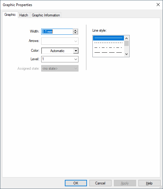
Graphic Properties - Graphic
To display/modify the properties of a graphic,
-
right-click on a graphic object, select Graphic Properties... from the displayed context menu and select the Graphic view. To select more than one object for modification, hold down the 'shift' key, then left-click on each of the desired objects and right-click on the final object to display the context menu.
-
Or left-click on a graphic object to highlight it (or for multiple objects, left-click on each object while holding down the 'shift' key), select Format -> Graphic Properties... on the Main Menu bar and select the Graphic view.
The following dialog box appears:

|
Graphic |
|
|---|---|
|
Width |
Defines the line width (thickness) of the graphic.
Note
Lines with a width of 0 mm are displayed and printed! |
|
Arrows |
Lines can have arrows on one or both ends, depending on the option selected from the drop down list. |
|
Color |
Defines the color of graphic elements.
If 'Automatic' is selected, the color defined in the Color Definitions dialog box will be used. |
|
Level |
Defines the drawing level on which the graphic elements will be placed.
|
|
Assigned state |
Displays the symbol state assigned to the symbol graphic.
See also: Electrical Checks - Overview |
|
This option is only available when editing graphic of symbols of type ' Table'.
Table graphic must be assigned to the table's header, row or footer.
Example
See also: Formboard |
|
|
Graphic for sealed pin |
This option is only available when editing graphics of sealed pins.
Defines the numbering of all selected sealed pins.
See also: Assigning graphic to sealed pins
NoteTo remove the display of sealed pins on a connector master symbol enter the value 0 in this number field. |
|
Line style |
Defines the line style to be used. |
|
Changeable symbol graphic |
This option is only available when editing graphic rectangles and lines of
NoteThis option is not available with ovals, circles, polygons, arcs, arcs (3 points).
Concerning 'Twisted pair symbols', at least one graphic line must be able to be modified, otherwise it is impossible to save them to the database.
When this option is checked, the symbol graphic's size can be changed in project. |
