Table Symbols
This functionality is only available, when a E3.formboard license is present!
Each device has a table assigned that lists the original pin, target pin and wire information per connection.
A table symbol looks as follows (the legend does not belong to the table; it serves as an explanation only):

Definition in Database Editor
To define a new table symbol a 'normal' symbol is created first.
The Table type must then be defined in the Symbol Properties... in Database Editor mode. The X and Y Offset can also be specified for the rows.
This offset defines the number of units, by which the next row is moved when replicating. The offset is valid for the complete table symbol and must thus be defined only once.
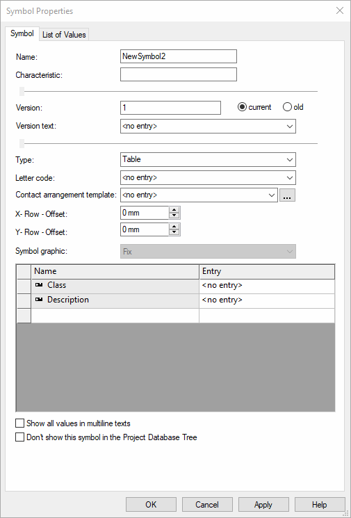
For a more detailed description on how to create a table symbol in DBE mode, see also Defining Table Symbols.
Placing Table Symbols
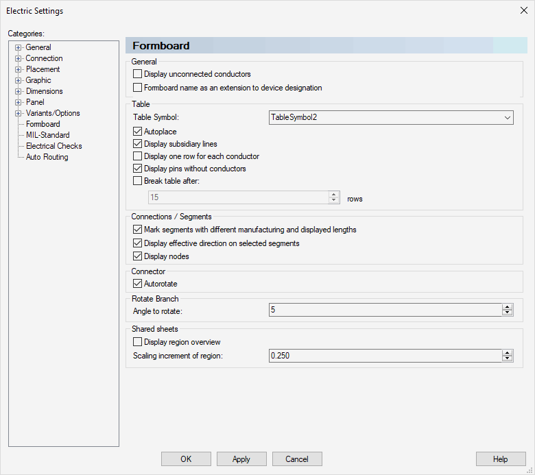
Which table symbol is assigned to a device can be defined in Tools -> Settings -> Formboard. One table symbol can be defined per project.
Note: The following is valid when placing
-
The table's header remains unchanged when dynamically replicating the rows.
-
The table's rows are copied and moved according to the offset.
-
The table's footer is moved under the last row replicated.
-
A table must always be placed on the same formboard sheet as the formboard view.
Manually Placing
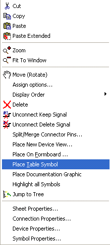
Only one table can be added to a formboard view using the Place Table Symbol command from a view's context menu.
When a table is already placed for this view, the command is not available.
Autoplace
Since a table is almost always required for a device, the Autoplace option is available for tables.
This option is only active when a table symbol is defined. With this option checked, the table symbol is displayed at the cursor position after placing the device. This operation can be aborted using the ESC key.

Displaying Table Subsidiary Lines
How table subsidiary lines are displayed to the device can be controlled using the Display Table Subsidiary Lines button ![]() or the Display subsidiary lines option in Settings -> Formboard.
or the Display subsidiary lines option in Settings -> Formboard.
Laying Wires/Conductors in Formboard Table Symbols
It is also possible to lay conductors on table lines. To do so, please proceed as follows:
-
As soon as a cable is inserted into a project, the individual conductors are displayed in a subordinated tree of the cable in the project window and can thus be laid by simply dragging and dropping them onto the work sheet.
-
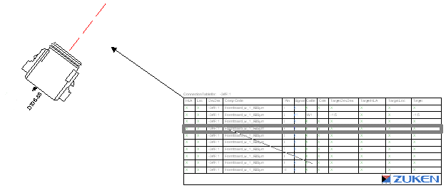
Then place any conductor on a table symbol by positioning the cursor over a line. When selecting the start and end points in the table line, the line is highlighted.
Note
This function is available only if graphic elements in database editor mode were defined for a table line. If only line text but no line graphic was defined, the line cannot be selected.
Displaying Table Row for Every Wire in Table Symbol on Formboard Sheet
When the Display one row for each conductor option is checked in Settings -> Formboard, redundant texts that may exist due to multiply placed conductors/wires.
These redundant texts (e.g. pin names) may confuse the table layout. To not display texts that are valid for all conductors/wires, sub rows can be defined.
See Example

If no Sub row table element is defined for this table symbol in the database, the values are separated by commas.
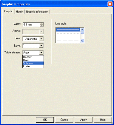
The Sub Row is defined as a Table element in the Graphic Properties or Text Properties in DBE mode:
Breaking Table in Formboard Table
The display of the table symbols is much clearer when the information is placed side-by-side, instead of one below the other. That's why it's possible with the Break table after ... rows option in Settings -> Formboard to specify the number of rows before the table is broken.
Missing rows are automatically grayed-out; the headers and footers are duplicated:

Table Symbols Adapted to Defined Variant/Option
Table symbols are adapted according to defined variant/option. By using the following settings the display can be changed:
-
Tools -> Settings -> Formboard -> Display one row for each conductor
-
If the option is active, for each conductor or wire that is connected to a pin, is displayed in a separate row of the table. Pins without placed conductor / wire are not displayed.
-
-
Tools -> Settings -> Variants/Options -> Display -> Draw other variants/options colored
-
If the option is active, the entire table is always generated. The objects found in an inactive variant/option are identified by the defined color and can no longer be edited.
If the option is inactive, the table rows that are in an inactive variant/option are suppressed.
-
The following rules are for suppressing (or shading the table rows):
-
If the connector is in an inactive variant/option, the entire table is suppressed.
-
If a pin of the original connector is in an inactive variant/option:
-
The table is generated with the unchecked option Display one row for each conductor:
The corresponding row is completely suppressed, independent of the variants/options of the connected conductors/wires.
-
The table is generated with the checked option Display one row for each conductor:
All rows of the corresponding pin are completely suppressed, independent of the variants/options of the connected conductors/wires.
-
-
If a conductor or wire is in an inactive variant/option:
-
The table is generated with the unchecked option Display one row for each conductor:
The conductor-related texts are removed from the text nodes in the table.
-
The table is generated with the checked option Display one row for each conductor:
All rows representing the corresponding conductor or wire are suppressed.
-
In the following example the pink enclosed area shows the original connector with both above-mentioned settings unchecked, additionally all options are active:
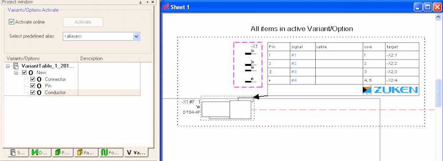
In the following example both settings are unchecked and pin 4 has been deactivated:
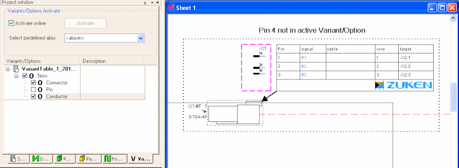
In the following example both settings are inactive and the conductors have been deactivated:

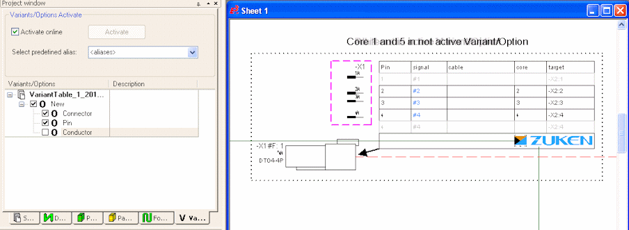
In the following example the pink enclosed area shows the original connector with both above-mentioned settings checked, additionally conductors 1 and 5 have been deactivated:
