Modifying an Existing Component/Wire Group/Connector/SubCircuit
This chapter comprises information on modifying an existing component using the Edit command displayed by right-clicking on the respective component in the Component or Model view of the Database Window.
Selecting the Update in Project command on the modified object upon modification will 'transfer' the changes to the respective objects used in project.
Modification of an existing component (standard device/terminal/cable)
To modify a component,
-
in the Component tree view of the Database Window, right-click on the component to be modified, and select the Edit command on the displayed context menu.
If the Database Editor has not been activated yet, it will automatically do so.
The component sheet will be opened displaying the component (depending on which component has been selected, it may contain symbols, modelsconductors when editing a cable etc.) ready for modification.
-
Activating the Save to database command will display a message box asking to save.
If the modified component is used in project, the user will be informed that the structure of this component is used in x components.
These components are immediately listed in the Results view of the Output Window.There are two possibilities to continue: either to create a new structure for this component or to change all.
Modifying a dynamic component / component without structure using the Edit command selected from the displayed context menu will start the Component Wizard.
Modifying an existing wire group
To modify a wire group,
-
in the Component tree view of the Database Window, right-click on the wire group to be modified and select the Edit command from the displayed context menu. The Database Editor will start automatically, if it has not been activated yet.
The Component Properties dialog box also containing the Wire Group tab will be displayed ready for editing. The wire group's version text, its device letter code and attributes can be modified.
Modification of an existing connector
To modify a connector,
-
In the Component tree view of the Database Window, right-click on the connector to be modified, and select the Edit command on the displayed context menu. The Database Editor will start automatically, if it has not been activated yet.
The connector is displayed on the working area (drawing sheet) ready for editing.
Name and Version of the connector cannot be modified, if it already exists in the database.
The following properties of the connector can be edited graphically on the sheet:
General Remarks
All symbols on a drawing sheet can be replaced with another symbol of the same type.
To do so, right-click on the symbol to be replaced and select Symbol Properties from the displayed context menu. The Symbol Properties dialog is displayed where a different symbol can be selected from the drop-down list.
Pins can be modified, deleted or added in the Pin Names dialog box that is displayed after right-clicking anywhere on the sheet and selecting the Pin Assignment... command from the displayed context menu.
Component Properties and Pin Properties can be modified by right-clicking anywhere on the sheet and selecting the Component Properties command from the displayed context menu, to display the Component Properties dialog (see Component Properties and Pin Properties).
It is also possible to define the connector's mating connectors and connector pin terminals in this dialog. Dependent on what has been selected in the tree view, the attributes are valid for the complete connector or only for the selected pin.
It is possible to define several mating connectors and connector pin terminals.
|
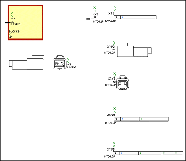
A block is always placed in the top left corner of the sheet. It cannot be modified or deleted - it can only be moved.
It serves for displaying the block-connector symbol of the connector (if one exists).
The block symbol can be deleted from the block or exchanged using the Symbol Properties. Only one symbol can be placed on the block.
When deleting the block-connector symbol, the related symbol is removed from the component. A new symbol can then be placed to add it to the component.
In addition, a block-connector symbol can be dragged from the Symbol Tree onto the block border and any existing connector on the block will be deleted and replaced by the new one. |
|
|---|---|
|
When creating a connector, any existing connector master symbol is shown below the block.
It can be edited like the block-connector symbol (Drag&Drop, Delete) or exchanged using the Symbol Properties and only one connector master symbol is allowed per connector. |
|
|
The free connector symbol, i.e. one that is not placed on a block, is shown to the right of the block. It should not be deleted as otherwise all connector view symbols are removed as well.
This symbol type must always exist. In case it is not available, the system uses the first corresponding symbol that is placed on the sheet as a free connector symbol. It will then be impossible to remove it completely. |
|
|
In addition to pin representations, it is also possible to have other intelligent views (as opposed to documentation graphics) for the connector, e.g. Pin/Signal tables, Plan views, etc. In order to store additional view symbols for a connector in the database, they are simply added on the sheet.
Existing view symbols of the connector are placed to the right of the free connector pin. Additional views are displayed underneath each other.
There are 2 ways to add a view symbol:
These views can also be deleted or new connector symbols can be placed on the component sheet to define additional symbols for the connector views. Furthermore, it is possible to exchange the symbol using the Symbol Properties. |
Modifying an existing subcircuit
To modify a subcircuit,
-
in the Component tree view of the Database Window, right-click on the subcircuit to be modified and select the Edit command from the displayed context menu. The Database Editor will start automatically, if it has not been activated yet.
The Component Properties dialog box also containing the Subcircuit tab will be displayed ready for editing. The subcircuit's version text, its device letter code and attributes can be modified.
According to modification using the Edit command, a cable duct, a mounting rail corresponds to a subcircuit, i.e. the Component Properties dialog box will be displayed ready for editing.
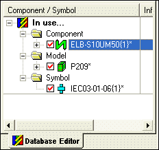
Components, symbols or models that have been changed since they were last saved to the database, are designated by an asterisk at the end of the component name in the Database Editor Window.

