
Block Functionality
Following sections contain detailed descriptions about the block functionality.
Inserting blocks
A block symbol is a rectangular black box that represents a subcircuit. The size of the rectangle can be modified.
It is possible to create variants/options for blocks - see Device Properties -> Block and Device Properties -> Device.
Select the Insert -> Block command on the Main Menu bar to display the Insert Block dialog box, where the desired block can be selected from the drop-down list box. The system automatically enters a Device Designation that can be modified if required.
To directly add a block without having to complete the dialog box, select one of the following options:
-
In the Misc Tree View of the Database Window, right-click on the desired block and select Place Block on the displayed context menu or
-
simply drag and drop the block symbol from the Tree View onto a drawing sheet or
-
select the Place Block button
 on the Place Toolbar. In this case the program selects the last placed block as the type of block for placement.
 -
In the Device Tree View of the Project Window, right-click on the Project folder and select Insert new block on the displayed context menu.
-
Right-click on an already placed block in the Device Tree view of the project window and select the Split block command from the displayed context menu.
If the block is placed by means other than the Insert Block dialog menu, the system automatically inserts a default Device Designation.
Further symbols and devices can be placed on an already placed block.
The following symbol types are supported:
-
'normal‘ symbols
-
block connector symbols
-
hierarchy port symbols
-
bundle symbols
-
attribute text template symbols (even
When placing devices on blocks there is a distinction between block connectors and 'normal' devices.
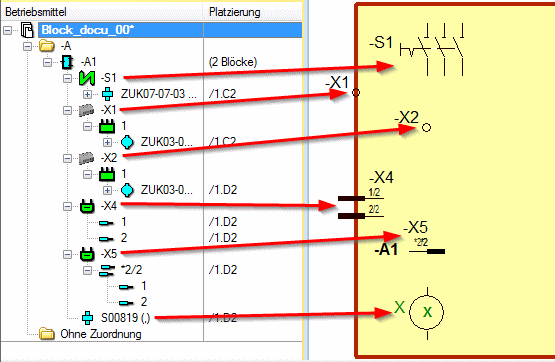
In the tree view of the devices all elements placed on the block / block edge are displayed below the block:
Note
At split blocks the number of blocks is also displayed within the info column Insert.
Resizing Blocks
Adjustments to the block size can be made by selecting the appropriate 'handles' on the block.
-
Blocks can be modified/resized:
-
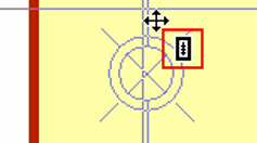
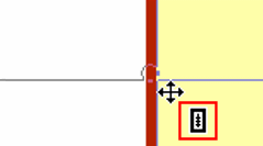
Left-click on a block to select it.
-
Press and hold the left mouse button over the modification handle of the selected block. The cursor will change to indicate that the handle has been selected. Alternatively, right-click on one of the handles and select the Modify command from the displayed context menu.
-
Move the cursor to produce the desired modification.
- During the modification process, the system will dynamically display the changes.
-
It is not possible to modify several blocks simultaneously.
Splitting Blocks
One unit (block) can be represented by several block symbols. In this way, a printed circuit board or an assembly can, for example, be documented on several sheets.
Splitting of a block has the following advantages:
-
Circuit diagrams that contain blocks with many connectors can also be drawn on small sheet formats.
-
Blocks can be divided into small functional units to provide a clear overview.
Note
When splitting blocks, the system uses the symbol graphics of the selected block.
When a block is split, it is possible to display one of the block's sides as jagged, which makes it clearly visible that this block is displayed several times.
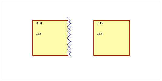
Display settings can be defined in the Split block section under Tools -> Settings -> Placement -> Block. To change these properties for example for an individual block later on, select the Symbol Properties - Graphic.
Block references
The reference text allows you to recognize individual blocks that belong to a set of split blocks. These references are automatically defined on separation of the block.
The reference type can be pre-defined in theTools -> Settings -> Placement -> Block menu. The settings apply to all blocks that are drawn after changes have been made to the settings, not to existing blocks.
The reference type of existing blocks can be changed in the Block View of the Device Properties context menu of a block.
To divide an existing block into several block symbols,
-
Right-click on a block and select the Split Block command from the displayed context menu.
-
Drag the block to the desired location on the sheet and left-click again to drop it at its new position.
-
Once positioned, the block can be re-sized as required.
Block connectors on split blocks
Block connectors can simply be dragged and dropped from one block symbol to another block symbol, provided that the block symbols belong to the same split block.
Inserting block connectors on a block
Block connectors can be placed along the block outlines.
To insert block connectors on a block:
Select the desired connector from the
-
Device Tree View (for unplaced connectors)
-
Component Tree View
and
-
drag&drop the desired connector (for the entire connector) onto the desired location on the block outline
or right-click on the connector and select the context menu command-
Place (For entire connector)
-
Place Single Pins (For single pin display)
Note: The connector can also be placed on two sheets in the single pin view
-
-
drag the connector to the desired location on the block outline and
-
drop with the left mouse button when an additional connector symbol appears:
Note
When a single connector pin is placed as block connector, all other pins of the connector can be placed as block connector only.
There are the following options to place a block component with block connector:
A block component with block connector can either be placed by the component tree of the database window or the component table:
-
Right-click on the desired block component with connector within the component tree and select the command Place with Connectors in the displayed context menu and afterwards place the block component at the desired location within the working sheet
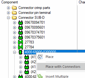
or
-
place the block with connector on the working sheet using drag&drop.
Note
When a connector is added to a block as block connector, the block connector's pin names can be changed regardless of how the names are defined in the original connector. The pin names are thus not transferred to the block connector upon changing the original connector.
The number of block connector pins cannot be changed. Therefore, changing the number of pins of the original connector is transferred to the block connector upon updating the block.
Summary
The number of block connector pins can be changed upon updating blocks. The pin names of block connector components are not changed upon updating blocks.
Inserting connectors with inserts on a block
Connectors with inserts can be placed on a block the same way as regular block connectors (see Inserting block connectors on a block).
Please consider the following limitations with block connectors:
-
Symbols of connector pin terminals of a connector with inserts that are placed on a block component, are deleted in the following cases and must be placed again:
-
If the connector pin terminal is a connector with inserts of the type Connector and itis exchanged with a cavity part of the type Connector with inserts, or
-
the connector pin terminal is a connector with inserts and is exchanged with a cavity part of the type Connector.
-
-
Symbols of connector pin terminals of a connector with inserts (for example with the device designation -X1) that are placed on a dynamic block, are not deleted when exchanging with a connector with inserts, but rather receive a new device designation (for example -X2).
The exchanged connector with inserts is then displayed in the Device tree view with its original device designation (-X1) as unplaced in the structure of the connector with inserts.
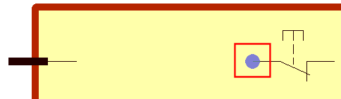
Inserting devices on a block
Normal devices can be placed within the block.
Note
In addition, a terminal can be placed along the block outlines.
To insert a device on a block
Select the desired device from the
-
Device Tree View (for unplaced connectors)
-
Component Tree View
and
-
drag&drop the device onto the desired location on the block or block outline (for terminals only)
or -
right-click on the device and select the context menu command Place,
-
drag the device onto the desired location on block or block outline (for terminals only)
-
and drop with the left mouse button when an additional device symbol appears
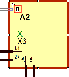
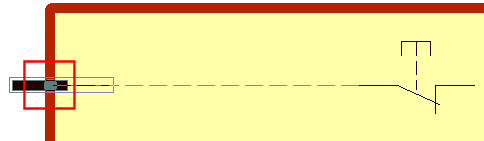
Example Device on Block
Example Terminal on Block Outline
Note
-
When placing components with several symbols, all placed symbols must be placed within the block
-
When placing assemblies, all placed symbols of the assembly must be placed within the block
-
Only views of the connectors, terminals and devices placed within the block can be placed
-
A block can't be placed within a block
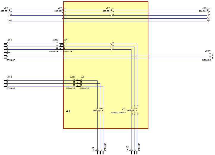
Connections in blocks
Please keep in mind the following regarding connections in blocks
-
Devices within a block and also block connectors can be connected with one another
-
The following connections are possible:
-
Connections to objects placed on the block border
-
Connections to objects placed within the block
-
Internal connections within the block
-
Connections crossing through the block
-
-
For devices placed on the block the snap point for connection lines is the device pin:
-
For block connector symbols placed on the block border the snap point for connection lines is on the block border:
-
If an attribute text template symbol is placed on a block, this symbol belongs to the block. When moving the block, the attribute text template symbol is also moved.
-
If an attribute text template symbol is placed on a connection line in the block, this symbol belongs to the connection line. When moving the block, the attribute text template symbol remains on the connection line.
Note
If all connection segments are located within the block, these are also moved as well as the attribute text template symbols.
Moving blocks
Please consider the following when moving blocks
-
When moving a block, the following objects are also moved:
-
All symbols and devices in the block and on the block's border (These elements are displayed underneath the block in the tree view.)
-
All connection segments located completely within the block. Connections across the block are not moved
-
Variants/Options on blocks
It is possible to create variants/options for blocks
see Device Properties -> Device
On creation of a variant for a block, the related variants are also created for all devices of the block.
When placing new devices on blocks, the system creates devices in all existing variants of the block.
It is not possible to create variants of block devices for variants within which the block has no own instance.
Note
-
If a variant contains instances of blocks, only instances of devices in the same variant can be placed on these blocks.
-
If a standard block contains instances of devices of a variant, it is not possible to create a new instance of the block for this variant.
Error messages displayed during placement of symbols on blocks
Symbols cannot be placed and error messages are displayed in the Messages tab of the Output Window:
-
if you try to drag a connector pin symbol, belonging to an existing, free connector (i.e. not a block connector), from the Device Tree View and drop it onto a block symbol (message: Invalid position - existing free connector devices cannot be placed on block symbols!)
-
if you try to drag a block connector symbol, from the Device Tree View, and drop it onto a block, when the connector has already been assigned to another block. The error message informs you of the name of the block to which the connector is assigned: (message: Invalid position - connector has to be placed on block symbol of device -A1=Ass1+loc1)