Placing Devices
Selecting the Topology Symbol
It is possible to define a neutral Topology symbol for components or functional units with their corresponding components in the Settings.
It is also possible to define a special topology symbol for each component in the Database Editor:
-
Select the command Tools ->Start Database Editor in the main menu,
-
right-click on a symbol or component in the Database Window's Symbol or Component tree view and select the command New Symbol from the displayed context menu.
-
Edit the desired topology symbol for the corresponding component and
-
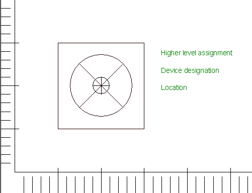
add the desired text types to the symbol, for example:
-
Higher level assignment
-
Device designation
-
Location
-
-
Then right-click on the symbol and select the command Symbol Properties from the displayed context menu,
-
switch to the Symbol tab,
-
define the symbol's Name,
-
and Attribute text template as Type, and
-
save the symbol to the database.
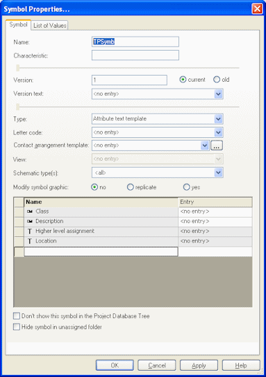
The newly created symbol can now assigned to the desired component in Database Editor:
-
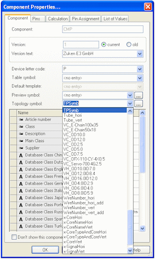
right-click on the component and select the command Component Properties from the displayed context menu and switch to the Component tab,
-
select the newly created symbol under Topology symbol,
-
and save the component to the database.
Placing Devices into Installation Space
Placement from within the Project Window
Devices from an already existing project (for example from a circuit diagram drawing) can be placed into an installation space on a topology sheet.
Note
-
When an already placed device is part of the selection, it will be ignored.
-
Assemblies with component assignment may not be placed into different installation spaces
To place one or more devices into installation space
-
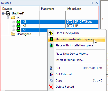
Select the desired devices via Multiselect and click the right mouse-button,
-
select the command Place into installation space and place the devices into the installation space on the topology sheet
or
-
select the desired device in the Device tree view and place it into the installation space on the topology sheet using Drag&Drop.
Placement from within the Database Window
It's also possible to place a component from within the Component database into an installation space on a topology sheet:
-
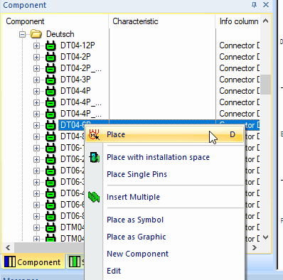
right-click on the desired component in the Database window's Component tab and select the Place command from the displayed context menu,
-
or select the desired component in the Database window's Component tab and place it on the topology sheet using Drag&Drop.
After a device has been placed into an installation space it can easily be moved to other installation spaced on the topology sheet.
Valid objects for installation spaces:
-
Objects from the database
-
Blocks
-
Connectors
-
Components
-
Assemblies
-
Symbols with functional unit(s) assigned
-
-
Objects from the project
-
Blocks
-
Connector devices
-
Devices
-
Assemblies
-
Functional unit(s) of symbol
-
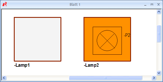
When a fill color is assigned an installation space, the block's color changes as soon as a device is placed therein. The block, i.e. installation space optically shows that all objects within the installation space are assigned a component. When the installation space still contains functional units without assignment, the color doesn't change and the user easily recognizes that the component assignment hasn't been finished yet.
Placing devices with installation space
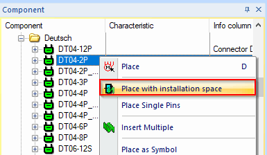
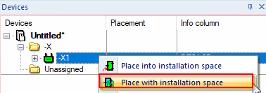
Devices can also be placed with installation space on a topology sheet. This takes place using the context menu command Place with installation space, which can be executed in the Device or Component Tree.
It is necessary to make sure beforehand that a corresponding installation space symbol is predefined in the Settings.
To do so, there is the new selection field Installation space symbol: in the Settings in the section Symbols under Topology:
If an installation space symbol is predefined in the Settings, the device with installation space can now be placed on a topology sheet.
To place a component or an unplaced device with installation space
-
right-click on the desired unplaced device/component (multi-select also possible) in the Device or Component Tree
-
select the context menu command Place with installation space:
Command in Component Tree
Command in Device Tree
-
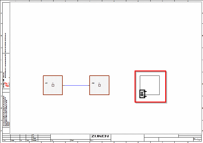
now place the installation space with the device(s) at the desired location on the topology sheet:
Signal Logic Lines Support Placing and / or Moving Functions
While and after placing or moving functions, it's possible to display signal logic lines:
To do so, activate the 'Display signal logic lines' button in the Functional Design toolbar: ![]() or activate the Display logic lines on block connections options in the Topology settings.
or activate the Display logic lines on block connections options in the Topology settings.
The signal logic lines are displayed when...
-
...placing and moving functions;
-
...moving functional blocks;
-
...for placed functions whose ports are not routed.
Special Handling of Connection Ports with 'GND' Port Type
The 'GND' port type is treated as a physical ground connection (contact without connection).
When a closed net contains a connection port of the 'GND' port type, no logic line is displayed to unconnected installation spaces with the 'GND' port type.
Displaying Pins of Installation Spaces with Symbol
Display example
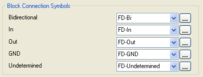
Block Connection Symbols definition in the Topology settings
Display result in the drawing

-
Incoming signals are represented by an arrow going into the pin.
-
Outgoing signals are represented by an arrow going out from the pin.
-
Bidirectional signals are represented by an arrow going into and out of the pin.
-
GND signals are represented by a box containing a rotated square at the pin.
-
When more signals or no signal at all are assigned, a rectangle is shown at the pin.
Adding or Deleting Connection Ports to Installation Spaces / Connecting or Disconnecting Selected Ports
To add a connection port to an installation space
-
right-click on the desired installation space in the drawing and select the command Device Properties from the displayed context menu,
-
switch to the Functional Ports tab,
-
right-click in the lower part of the dialog and select the context menu command Add connection port, and
-
assign the new connection port to an existing dynamic functional unit in the Functional Unit column, or in doing so, create a new dynamic functional unit that is assigned the connection port.

The manually added connection port can be deleted using the context menu command Delete Connection Port.
To create a connection through the installation space and thus connect ports with each other or to additionally lead a physical connection outwards (i.e. external connection),
-
either enter the same number for both desired ports to the Signal Equivalence column, or
-
select the desired rows in the dialog and select the Connect Selected Ports command from the context menu.
Afterwards, the dynamic connection port automatically gets the functional port's signal.
To disconnect the connection between the ports,
-
change the previously entered number for the desired ports in the Signal Equivalence column, or
-
select the desired rows in the dialog and select the Disconnect Selected Ports command from the context menu.
One or several connection ports can be assigned a symbol from the database with assigned functional unit by right-clicking in the corresponding row(s) of the connection port(s) within the dialog and selecting the Assign Functional Symbol command from the displayed context menu.
The following dialog box appears:

The List options offer the possibility to select whether the symbol to be used has the same or a higher number of ports.
The desired functional symbol can then be selected under Symbol.
Same Signals in One Installation Space Automatically Defined as Equivalent
When several signals with the same signal name are placed in one installation space, those same signals are automatically defined as equivalent. When an equivalent signal is routed from one installation space running over a connect line to the next pin, only one signal is routed, however the other signals with the same name are still equivalent.