
Creating Functional Design
This functionality is only available, when a E3.functionaldesign or E3.topology license is present!
All functional design specific interface elements, functions and commands are only available, when the user has the appropriate license.
Therefore, start the application with the corresponding start parameter (command line parameter /functionaldesign).
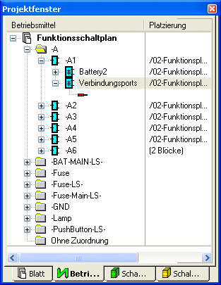
Displaying Functional Units and Their Ports in the Project Tree View
The display of the Functional Units can be controlled in the Tree Control Properties... by checking the Functional Objects option.
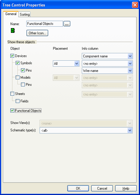
For functional units and ports can be defined under Placement, whether
-
All,
-
only the functional units and ports that are placed or
-
only the unplaced functional units and ports should be displayed.
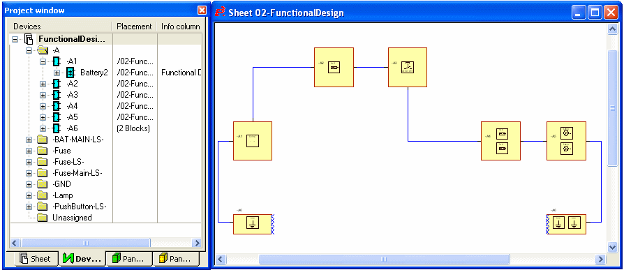
In case functional blocks are displayed in the Project tree view, the placed functional units and their ports are always displayed below their block. Unplaced functional units are displayed in the <Functional Units> folder.
In case symbols are displayed in the Project tree view, the symbol is displayed below the functional unit that was loaded to the project.
Inserting a Functional Design Sheet
Before creating a functional design, a so-called Functional design sheet must be added using the Insert -> Sheet command.
Select the required sheet format in the dialog and select the Functional Design sheet Type.

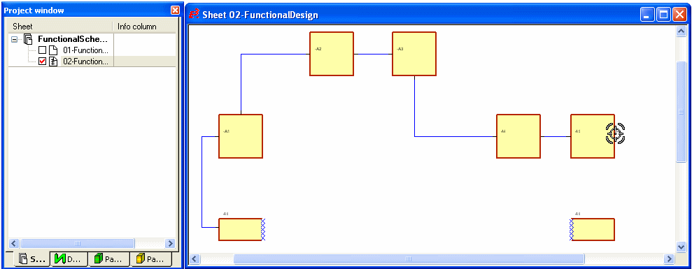
The project tree displays a special icon for the Functional Design sheet:
![]()
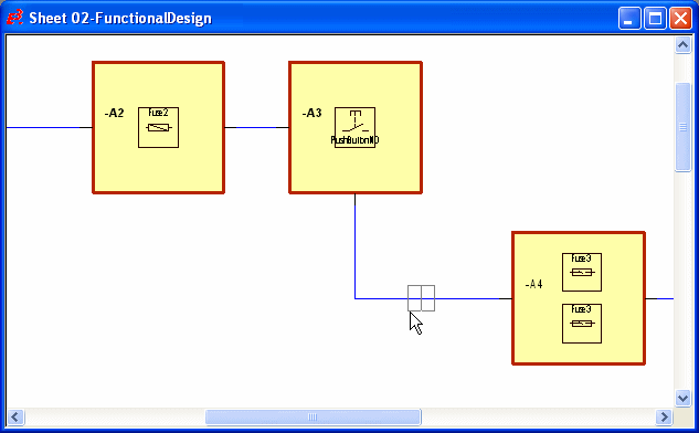
Placing and Connecting Functional Blocks
To display functional units so-called functional blocks are used. Standard blocks are used for placing a functional block. They are automatically assigned the corresponding designation Functional Block when placing on a functional design sheet.
This designation can be changed in the Device Properties -> Block dialog. This designation can only be changed as long as no functional units are placed on the block. Split functional blocks are also supported.
These functional blocks can be directly connected to each other. To connect the block use the familiar connect command:
-
By selecting the Insert -> Connection command from the Main Menu bar, or
-
by using the short cut C, or
-
by pressing the corresponding Insert Connection
 button.
The connection cursor changes shape when the mouse is moved across a block border:
Placing Functional Units, Changing Properties, Deleting Placement and Defining Display
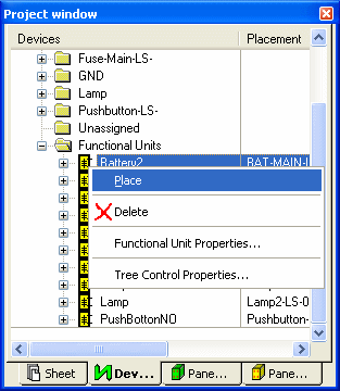
Now place the desired unplaced functional units from the Functional Units folder in the Device tree view via Drag&Drop or using the Place command from the context menu into the functional blocks.
It's also possible to place functional units directly from the Database tree view. When placing a functional unit without attribute template symbol the cursor correspondingly changes shape. See example:

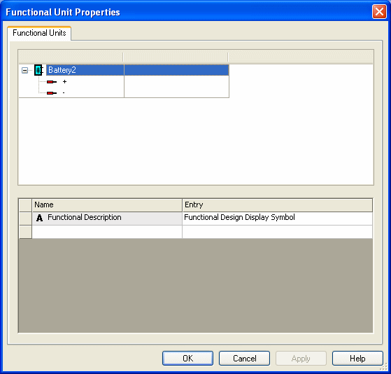
To display or modify the properties of a functional unit:
-
with the required functional unit selected in the drawing, select the Format -> Functional Unit Properties... command from the Main Menu bar, or
-
right-click on a functional unit in the drawing , select the Functional Unit Properties... command from the displayed context menu or
-
right-click on the desired functional unit in the Device tree view and select Functional Unit Properties... from the displayed context menu.
The following dialog box will be displayed:
At the same time, signals are routed through the connection lines. The signal name is either displayed in the Connection Properties -> Functional Port Connections dialog or in the connection's tooltip.
The dialog displays the End 1, the Signal Name and the End 2.

If several ports are connected in a net with the same signal, the connected signals are listed sorted by their signal names in the Connection Properties -> Functional Port Connections dialog and in the tooltip.
By deleting the functional unit on a functional design sheet only the display of the functional unit is changed (i.e. it's no longer displayed on the sheet). But, the functional unit still belongs to the functional block and is thus still displayed below the functional block in the Device tree view. Only by deleting the functional unit in the Device tree view the functional unit is removed from the block and afterwards displayed in the 'Functional Units' folder.
All functional units used in the project can be updated using the Update functional units in project command in the Database tree view.
The graphical representation of the functional units displayed on the functional blocks can be controlled in the Settings under Tools -> Settings -> Functional Design using the Show graphical representation of functional units option:

The button Show
graphical representation of functional units ![]() can be used to control the display and this
button can be selected under Tools
-> Customize
-> Commands.
can be used to control the display and this
button can be selected under Tools
-> Customize
-> Commands.
Adding Additional Connection/Functional Ports and Defining Signal Equivalence
Select the Device Properties -> Functional Ports command on a functional block, to add additional connection ports and to define the signal equivalence.
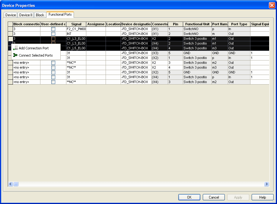
Add or Delete Connection Ports/Connect or Disconnect Selected Ports
A new connection port can be added by selecting the Add Connection Port command from the context menu, to lead an additional physical connection out of the block or to define connections as 'connected with each other'.
Thus, any signal and port name can be defined in the appropriate columns. The system predefines the Connector and Pin columns immediately after defining a block connection.
The column Functional unit indicates whether a dynamic connection port was added, by displaying: Connection Ports. Dynamic connection ports are correspondingly displayed in the Device tree view.
The manually added connection port can be deleted using the Delete Connection Port command from the context menu.
To create a connection through the functional block and thus connect ports with each other or to additionally lead a physical connection outwards (i.e. external connection),
-
either enter the same number for both desired ports to the Signal Equivalence column, or
-
select the desired rows in the dialog and select the Connect Selected Ports command from the context menu.
Afterwards, the dynamic connection port automatically gets the functional port's signal.
To disconnect the connection between the ports,
-
change the previously entered number for the desired ports in the Signal Equivalence column, or
-
select the desired rows in the dialog and select the Disconnect Selected Ports command from the context menu.
Disconnecting Connections Using Disconnecting Points
Block symbols can directly be placed on a functional connection as so-called disconnecting points.
Therefore, please select the appropriate block symbol from the Database tree view and select the Place Block command or Drag&Drop it directly onto the desired functional connection:
Block symbols can only be inserted to functional connections as long as they are not rotated or at least only rotated by 90°.
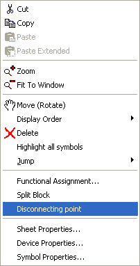
Afterwards select the Disconnecting point command from the context menu on the block, to define the block as a disconnecting point and to transfer the signals of the connection.
Please note, it's not possible to add functional units to functional blocks that are defined as disconnecting points.
Using the Functional Assignment... command selected in the context menu on a disconnecting point (on a sheet or in the tree view), it's possible to assign disconnecting points to a database connector.
Later on, the mating connector of the selected connector component is automatically placed in the Wiring Diagram.